 |
|||
|
|
|||
|
Page Title:
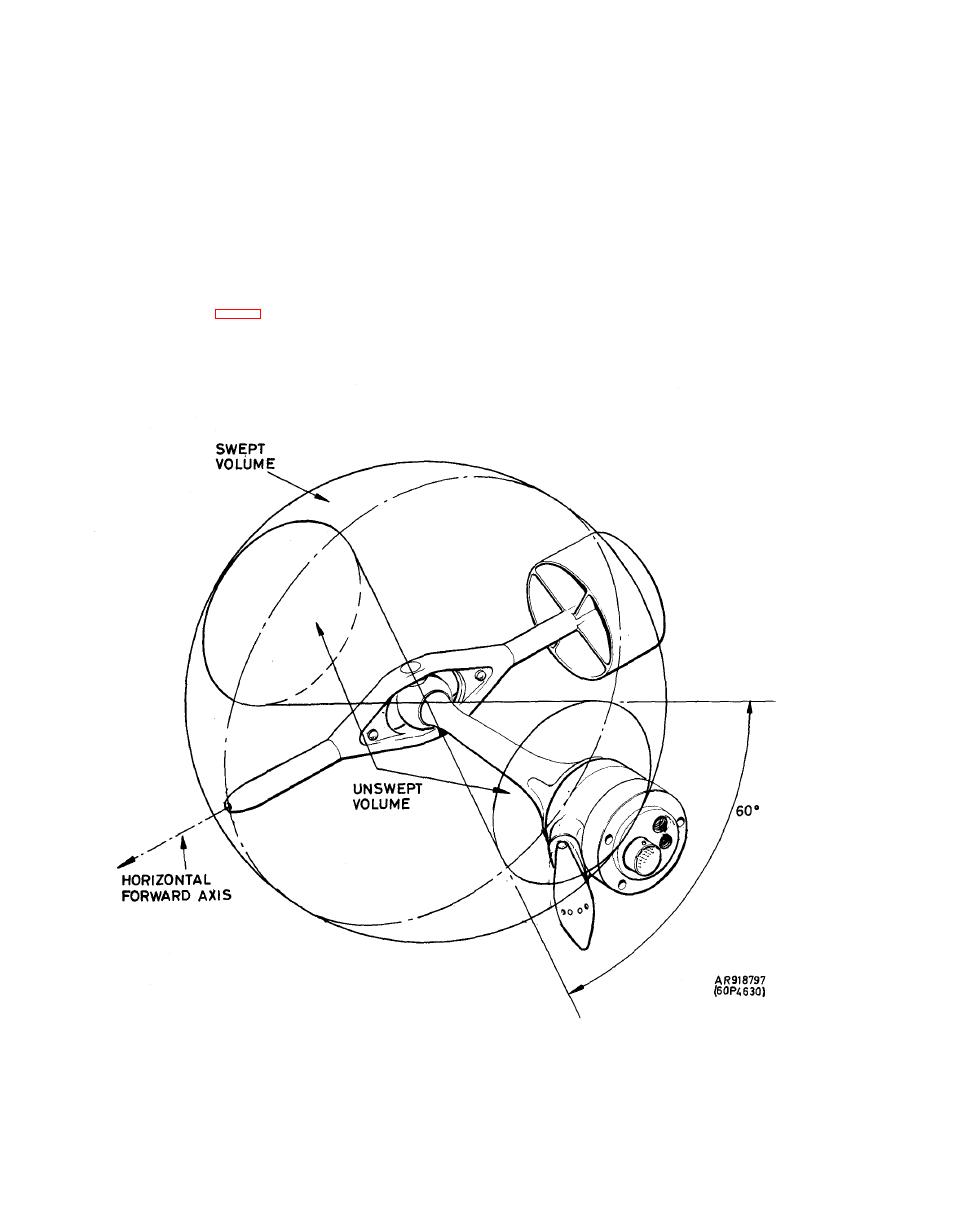
Figure 1-9. AADS Angular Freedom. |
|
||
| ||||||||||
|
|
 TM 9-1270-219-13&P
c. The pressure head is equipped with a heating
errors on either pressure. These pressures are conveyed via
e l e m e n t which provides anti-icing capability.
the shafts of the gimbal and helicopter plumbing to the
EPU.
b . Movement of the gimbal arrangement also causes
d . An Air Temperature Sensor (ATS) is attached to
two angular resolvers to generate electrical signals
the body of the AADS, at an angle such that it does not
r e p r e s e n t i n g the movement of the head in pitch and yaw
interfere with the airflow over the pressure head or pick
axes
relation
to
the
helicopter.
These
signals
are
up heated air from the flow around the head.
transmitted to the EPU where, together with the pressure
signals, they are used to compute airspeed and direction.
T h e gimbal arrangement permits total angular freedom in
A A D S p h y s i c a l D e s c r i p t i o n . The AADS consists
p i t c h and 120 in yaw (fig. 1-9); this allows the head to
of six main assemblies: a head assembly, a tail assembly, a
sense accurately the local impact and static pressures over
neck assembly, a body and plug assembly, a cover and
an airspeed range of up to 223 knots forward, 32 knots
dowel
assembly
and
a
plate
and
connector
assembly.
sidewards and 32 knots aft.
|
|
Privacy Statement - Press Release - Copyright Information. - Contact Us |
