 |
|||
|
|
|||
|
Page Title:
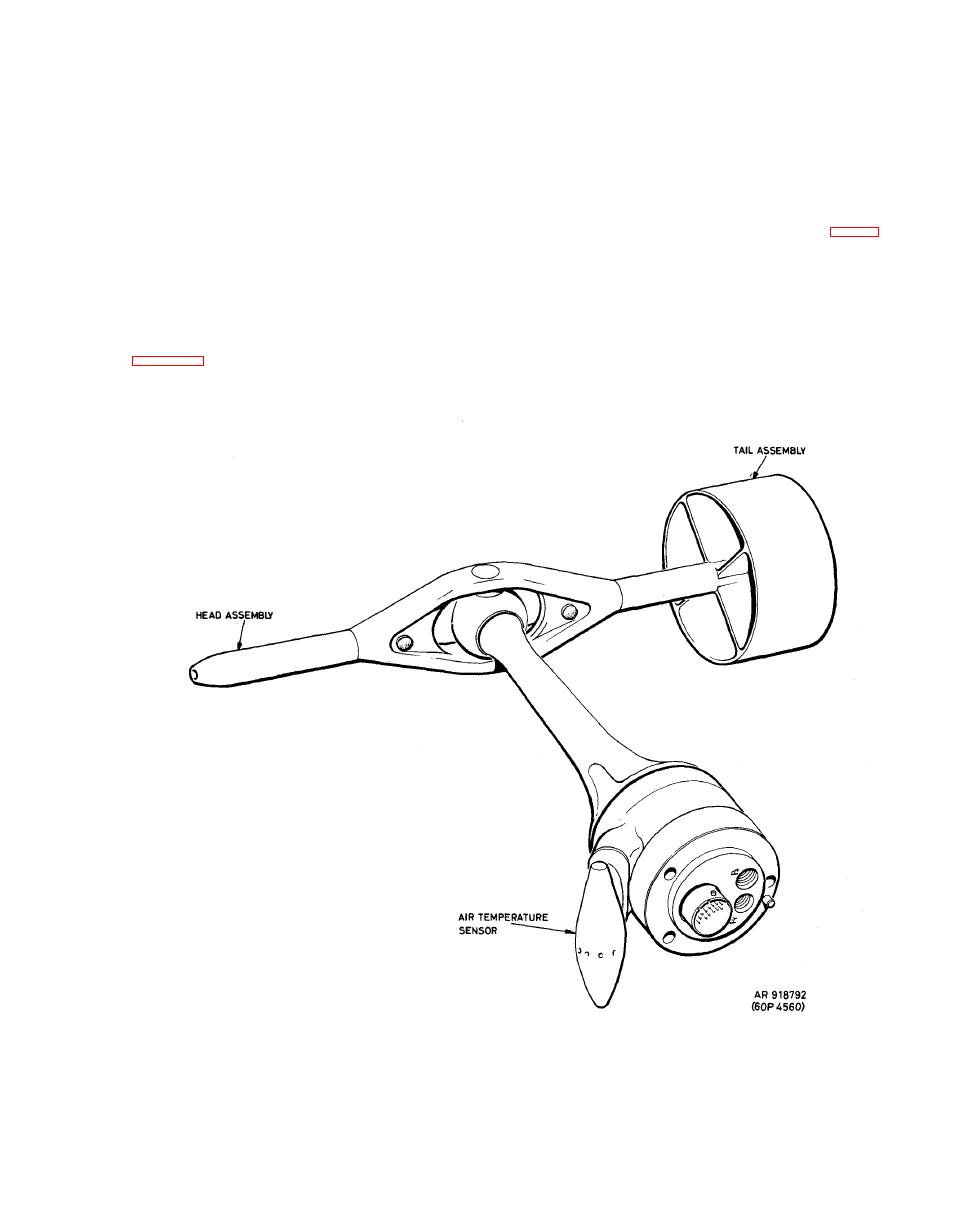
Figure 1-8. Airspeed and Direction Sensor. |
|
||
| ||||||||||
|
|
 TM 9-1270-219-13&P
signal to the Fire Control Computer and
output
interfacing
within
the
EPU.
Outputs
from
the
P
and
TA
ABS
IR
EPU are available in serial digital and dc analog formats to
supplies analog TAS signal to the Doppler Navigation
interface with the Fire Control Computer (FCC) and the
Subsystem. An analog radar altitude signal is fed to the Air
AN/ASN-128
Navigation
System.
Data
Subsystem
from
the
Radar
Altimeter
to
provide
ground effect error correction.
c. Component airspeed outputs from the EPU are
AADS
General
D e s c r i p t i o n . The AADS (fig. 1-8)
Airspeed
Indicator
(LAI),
a
displayed
on
the
LOW
has a pitot-static pressure head which is supported on a
standard
3
inch
indicator
which
displays
forward
and
g i m b a l arrangement and is caused to point into the local
lateral components of airspeed up to 50 knots in any
airflow by a finned tail.
direction.
S y s t e m T i e - i n . Connections between the Air Data
a. Both total and static pressure are sensed by the
Subsystem
and
other
helicopter
systems
are
shown
in
head which is always aligned with the local resultant
airflow
and
therefore
does
not
suffer
from
incidence
|
|
Privacy Statement - Press Release - Copyright Information. - Contact Us |
