 |
|||
|
|
|||
|
Page Title:
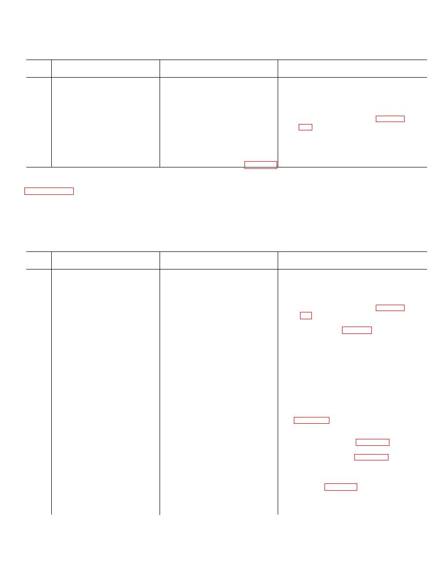
Table 2-8. Troubleshooting of Laser Ranging Commander's Control C-9134/VVG-1 (A79) cont'd |
|
||
| ||||||||||
|
|
 TM 9-1240-369-34
Table 2-8. Troubleshooting of Laser Ranging Commander's Control
C-9134/VVG-1 (A79)-Continued
Item
No.
Malfunction
Probable cause
Corrective action
7
RANGE RETURN SELECTOR 1
9.
Purge unit (TM 9-2350-230-12).
or 2 lamp does not illuminate-
continued.
8
System does not operate.
LASER MODE CONTROL switch.
1.
Install failed unit in hot mo ck-up.
2.
Perform portion of checkout (para 4-2a
or 4-2b) which will duplicate
malfunction.
3.
Remove unit from hot mock-up.
4.
Return unit to depot for repair.
in table 2-9. This table is to be used at general support
2-11.
Troubleshooting
of
Laser
Receiver-
maintenance level after organizational maintenance has
Transmitter RT-1021/VVG-1 (A76).
determined the malfunction exists in the receiver-
a. Test Setup. Set up hot mock-up as described in
transmitter unit.
b. Troubleshooting Procedures. All troubleshooting
procedures for the receiver-transmitter unit are contained
Table 2-9. Troubleshooting of Laser Receiver-Transmitter RT-1021/VVG-1 (A76)
Item
No.
Malfunction
Probable cause
Corrective action
WARNING
Ensure that power is off when installing or removing units in hot mock-up, or installing or
removing components or assemblies in units.
1
A "3" is displayed on the right
PFN current adjustment;
1.
Install failed units in hot mock-up.
RANGE (METERS) indicator
malfunction 3/buffer logic circuit
2.
Perform portion of checkout (para 4-2a
(unit A79).
card A76A1, PMT chassis
or 4-2b) which will duplicate
assembly A76A6, or flashtube V1.
malfunction.
3. Using R/T tester (para 2-6) check
receiver sensitivity and transmitter
output energy. If receiver sensitivity is
not within tolerance. continue with step
4. If transmitter output energy is not
within tolerance, continue with step 7.
If receiver sensitivity and transmitter
output energy are within tolerance and
malfunction exists. continue with step
9.
4. Remove R/T tester.
5. Replace PMT chassis assembly A76A6
6. Perform step 3 and continue with step
11.
7. Replace flashtube V1 (para 3-12h).
8. Perform step 11.
9. Replace A76A1 card (para 3-12e).
10. Perform step 3 and continue with step
11.
11. Perform receiver-transmitter u nit
alinement (para 3-12c).
2-35
|
|
Privacy Statement - Press Release - Copyright Information. - Contact Us |
