 |
|||
|
|
|||
|
Page Title:
Receiver-Transmitter Check and Adjustment |
|
||
| ||||||||||
|
|
 TM 9-1240-369-34
every 5,000 rangings. In addition, whenever there is a
2-6. Receiver-Transmitter Check and Adjustment.
requirement that the receiver-transmitter unit or the
power supply control unit be replaced or repaired, the
CAUTION
PFN current must be adjusted to produce the proper
Adjustment tool inserted into PFN
transmitter energy. The R/T tester and the PFN charge
ADJ access port shall be of an
ammeter check the transmitter energy, receiver
electrically insulating material to
sensitivity, and the PFN current.
The following
prevent
possible
damage
to
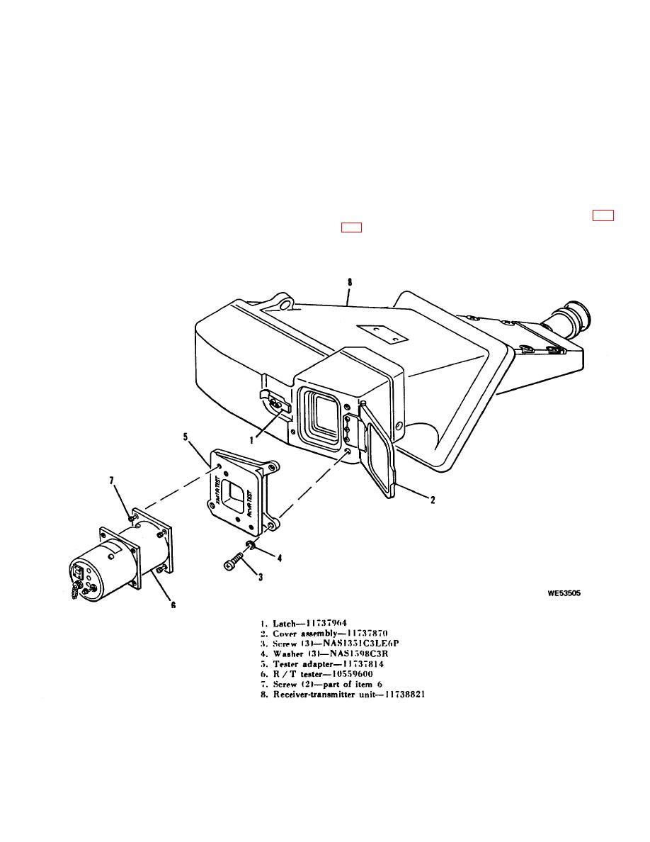
procedure is to be performed by securing the tester
equipment
resulting
from
tool
adapter and R/T tester to the receiver-transmitter unit
contacting exposed voltage point.
and interconnecting the PFN charge ammeter, and R/T
Excessive transmitter energy density
tester to the power supply control unit.
may damage the coating on the
b. PFN Adjustment Procedure.
The following
receiver-transmitter
unit
optical
procedure is used to prepare the R/T tester for use (fig.
elements.
a. General. The transmitter energy, which may be
altered by adjusting the PFN current, is to be checked
Figure 2-6. R/T tester installation.
2-9
|
|
Privacy Statement - Press Release - Copyright Information. - Contact Us |