 |
|||
|
|
|||
|
Page Title:
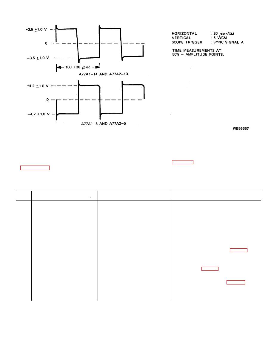
Figure 2-15. Sync signals A and B (battery power supply unit). |
|
||
| ||||||||||
|
|
 TM 9-1240-369-34
Figure 2-15. Sync signals A and B (battery power supply unit).
b. Troubleshooting Procedures All troubleshooting
2-10.
Troubleshooting
of
Laser
Ranging
procedures for the commander's control unit are
Commander's Control C-9134/VVG-1 A79).
contained in table 2-8. This table is to be used after
a. Test Setup. set up riot mock-up as described
organizational maintenance has determined the
malfunction to exist in the commander's control unit.
Table 2-8. Troubleshooting of Laser Ranging Commander's Control C-9134/VVG-1 (A79)
Item
No.
Malfunction
Probable cause
Corrective action
WARNING
Ensure that power is off when installing or removing units in hot mock-up, or installing or removing
components or assemblies in units .
NOTE
Unless otherwise specified, all switches, indicators, and test points are on the A79 unit.
1
When TSW switch is pressed,
Defective lamp, TSW switch, or
1.
Install failed unit in hot mock-up.
one or more do not illuminate.
logic circuit card A79A1.
2.
Perform portion of checkout (para 4-2a
or 4-2b) which will duplicate
malfunction.
3.
Replace lamp associated with
malfunction (para 3-9f).
4.
Perform step 2. If malfunction is not
corrected, continue to step 5.
5.
Remove unit access cover (para 3-9a).
6.
Using multimeter, measure voltage at
TP7 on A79A1 card
2-31
|
|
Privacy Statement - Press Release - Copyright Information. - Contact Us |
