 |
|||
|
|
|||
|
Page Title:
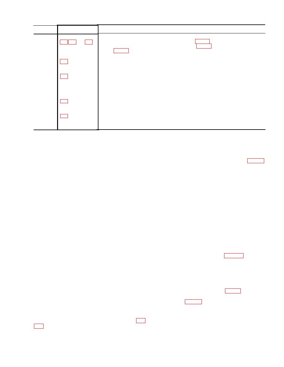
Table 2-1. Operator's Inspection Chart for Plotting Board M17 and Caring Case M72 |
|
||
| ||||||||||
|
|
 Table 2-1. Operator's Inspection Chart for Plotting Board M17 and Caring Case M72
Point of
Accepted standard
Figure
inspection
PLOTTING BOARD M17
When the azimuth disk is assembled on the base (fig. 12), it shall be rotatable to any
Alinement
required position. The index line on the base (fig. 1-3) and the centerline on the
disk (fig. 1-4) shall be in coincidence when the disk and the index mark on the
base are alined.
The azimuth disk shall be clean, flat, and in good condition as explained in the preced-
Azimuth
ing text and shall rotate freely on its central pivot point to any azimuth position.
disk
The pivot point shall be a snug fit on the pivot.
The base surface shall be clean, flat, and in good condition as explained in the pre-
Base
ceding text.
Pivot
The pivot, secured in the base, shall not be loose or bent.
CARRYING CASE M72
One snap fastener shall be secured in the carrying case. It shall not be destroyed or
Snap
fastener
loosened in the case fabric, and shall properly hold the cover flap in a secure and
closed position.
The loop of the carrying case is secured by stitching to the reverse or back side (not
Loop
shown in the illustration indicated). It shall be securely fastened to the case. The
stitching shall not be loose or torn.
(3) To determine the distance on the plot-
2-7. Operation
ting board from the first point to the second point,
a. The theory of operation of the plotting
divide the stated distance by 50 or 100 (depend-
board is simple and the accuracy of the results
ing on which scale on the grid pattern (fig. 13)
depends on the skill of the operator. The plotting
is used). The result is the number of squares on
board is used to plot accurately the relative posi-
the grid pattern between the two points. Count
tions of the weapons, base points, and targets
off the number of squares, or fractions of squares,
and to determine the directions and distances
thus determined from the first point toward the
between these points. The size of the dots placed
top of the plotting board and plot the second
on the plotting board affects the accuracy of the
point. The second point may be plotted also by
data determined. The dots shall be made as
measuring off the stated distance from the first
small as possible. To make it easier to locate
point toward the top of the plotting board using
these small dots, a small circle may be placed
the range scales on the disk.
around each slot. In computing the data, be
d. When the distance and azimuths to the tar-
careful to use the dot and not the circle. Pencils
harder than 2H and gritty erasers should not be
get firing position have been determined from
the observation post, the azimuth and range from
used on the transparent plotting surfaces.
the weapon position to the target position (WT
b. An arbitrary point on the disk may be se-
= w e a p o n to target) is determined as indi-
lected as the weapon position or the observa-
cated in (1) through (4) below.
tion post. Whenever possible, the center (pivot
(1) Use the pivot point (figs. 1-3 and 14)
point) of the plotting board is used to represent
as the observation post.
either the weapon position or the observation
(2) The locations of the firing position and
post.
the target, as obtained at the observation post
c. To plot a point with a given azimuth and
in terms of azimuth and distance, are plotted
distance from another point, proceed as indi-
individually on the movable disk.
cated in (1) through (3) below.
(a) Set the azimuth scale (fig. 14) gra-
duation corresponding to the azimuth over the
(1) Select an arbitrary point on the disk
index mark (fig. 13).
as location of the first point and place a pencil
(b) Mark each location with a pencil dot
dot. (If the pivot point is selected as the arbitrary
over the index line at the point on the range scale
point, it is not possible to make a pencil dot).
corresponding to the distance in meters. Each dot
(2) Rotate the azimuth disk on the base (fig.
is plotted toward the top of the plotting board.
(3) To determine the azimuth between the
the index mark.
2-3
|
|
Privacy Statement - Press Release - Copyright Information. - Contact Us |