 |
|||
|
|
|||
|
Page Title:
Figure 1-3. Plotting board M17--Base |
|
||
| ||||||||||
|
|
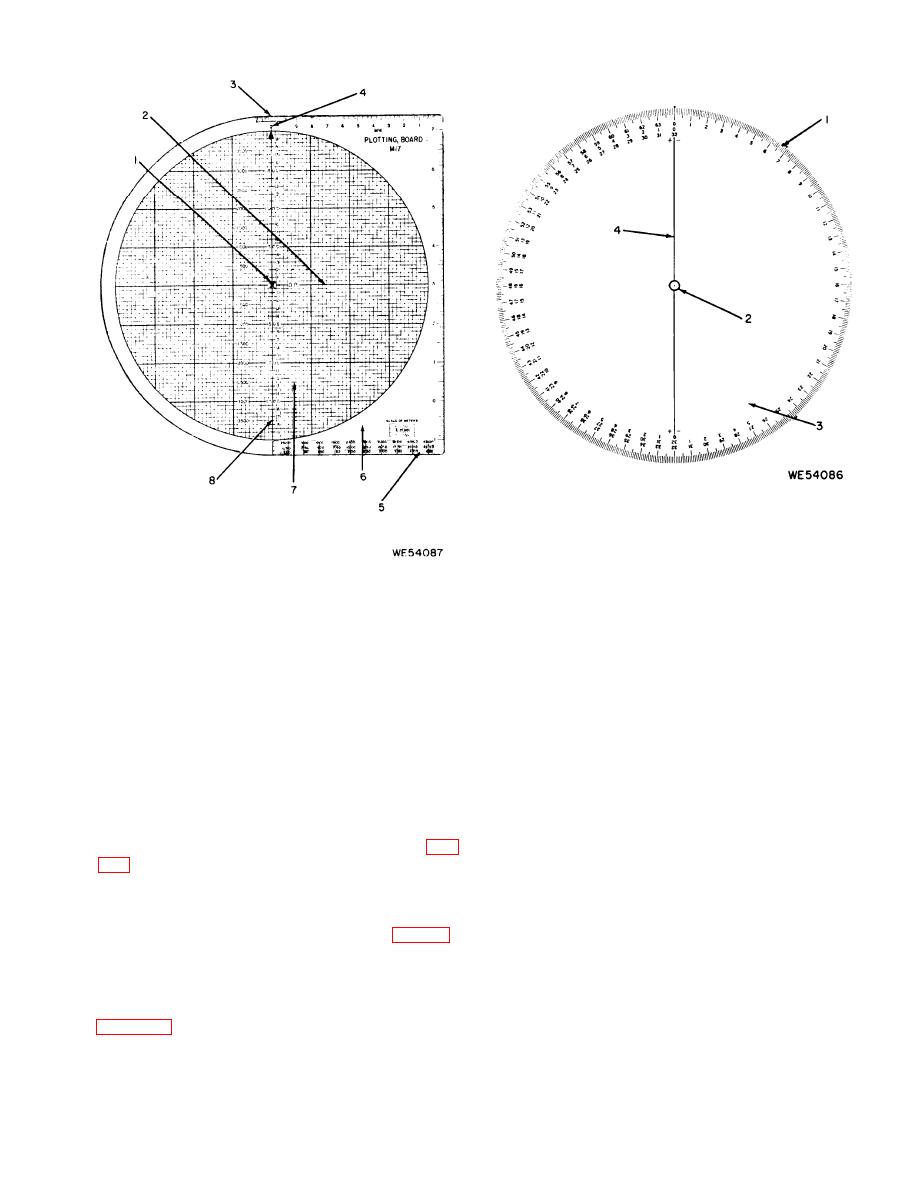 Figure 1-.4. Plotting board M17-azimuth disk.
pencil marks which can be erased following
completion of a problem.
Figure 1-3. Plotting board M17--Base.
( b ) A thin centerline (4) is printed
across the diameter of the disk and intersects
the pivot point (2). Red plus and minus marks
outward, above and below the pivot, from 0 to
are printed near both ends of the centerline for
2000 meters, in fifty meter increments and is
numbered from 1 to 19. These numbers are spaced
use in computing angles of site.
on every second horizontal fine line. Each small
(c) An azimuth scale (1) graduated in
square on the grid pattern is, therefore, 50 meters
mils is printed around the entire outer edge of the
on a side. The numbers to the left of the index
disk in a clockwise direction to conform to the
line indicate double values for the grid squares.
compass and is used to plot azimuth angles. This
Each small square is, therefore, 100 meters on a
scale is graduated in 10-mil increments from 0
side when the double value scale is used. How-
to 6400 and numbered at 100-mil intervals from
ever, any value may be assigned to the small
0 to 63.
grid square which best suits the problem at hand.
(d) A supplementary, middle mil scale
All marking is red.
having red figures is located on the plus side of
the centerline, running counterclockwise from 0
(2) Azimuth disk. The azimuth disk (fig,
to 32 and continuing on the minus side of the
centerline to 5. This middle scale is numbered
with graduations printed around the entire outer
in hundreds of mils. It is used in computing
edge and a centerline which runs through the
angles of site.
central pivot point (2). When the pivot point in
(e) A supplementary, innermost mil scale
the disk is on the pivot in the base (fig. 1-3),
also on the plus side of the centerline, begins
a n d the base is stationary, the disk can be
at a point 180 degrees from the 0 (zero) on the
rotated to all positions within 360 degrees. When
middle scale. This scale runs clockwise from 0 to
the disk is properly mounted on the base, the
32 and is numbered in hundreds of mils. It is
markings on the disk will appear as shown in
also used in computing angles of site.
(a) The surface of the azimuth disk (3),
c. Operation. The plotting board can be op-
facing the operator, is slightly roughened to take
erated in two positions.
1-3
|
|
Privacy Statement - Press Release - Copyright Information. - Contact Us |
