 |
|||
|
|
|||
|
Page Title:
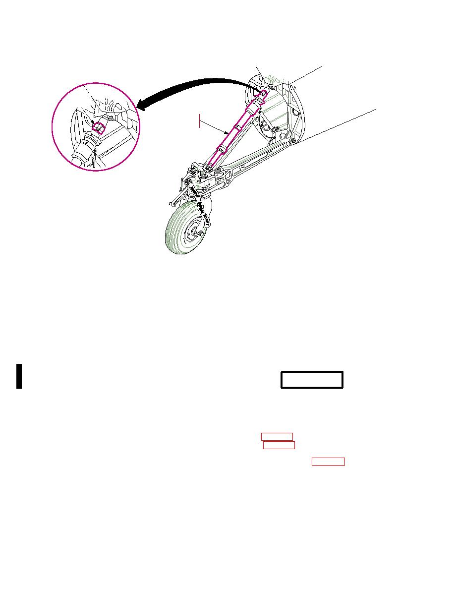
Figure 225. Installation of Tail Landing Gear Strut Lock |
|
||
| ||||||||||
|
|
 TM 55-1520-238-S
STRUT
LOCK
SHOCK
STRUT
M05-050
forward under drive shaft cover. Reinstall
d. Disconnect Vertical Stabilizer Forward
removed pushrod connection bolts, wash-
and Aft Electrical Wiring. Disconnect
ers, and nuts in related bellcranks.
two electrical harness plugs from their tail-
boom bracket receptacles; disconnect
h. Install Vertical Stabilizer Sling.
coaxial plug (P329) from trailing edge base
receptacle; and GPS antenna coaxial plug
(P1304), if installed, from receptacle. Tie
WARNING
disconnected plugs (P124) and (P1304) to
the intermediate gearbox, and tie plug
To prevent injury to personnel ensure
(P756) to the stabilizer aft bulkhead with
that stabilizer sling quick release pins
twine (D14). Remove two clamps from the
are fully bottomed and locked.
vertical coaxial lead.
Preadjust vertical stabilizer sling (item 47,
e. Disconnect Vertical Stabilizer Forward
and Aft Hydraulic Lines. Connect four
hydraulic quick disconnect fittings at lower
release pins in vertical stabilizer pin sock-
ends of stabilizer vertical structure.
ets, as shown (fig. 226). Pass fifth strap
f. Disconnect No. Five (Tail Rotor) Drive
through tail rotor pitch links and around the
Shaft. Remove five bolts from fan cou-
tail rotor drive shaft. With both ends of fifth
pling flange at the tail rotor drive shaft end.
strap on sling bar end eye, remove all strap
Retain removed coupling bolts.
slack at the tail rotor drive shaft, and secure
the fifth strap buckle.
g. Disconnect Tail Rotor Control Horizon-
tal Pushrod. Remove cotter pin, nut,
i. Aline Lifting Crane. Position the crane
washer, and bolt from both ends of
aft of helicopter tail. Aline crane lifting hook
pushrod. Discard cotter pins. Slide pushrod
over center of tail rotor gearbox fairing.
Change 3
|
|
Privacy Statement - Press Release - Copyright Information. - Contact Us |