 |
|||
|
|
|||
|
|
|||
| ||||||||||
|
|
 TM 55-1520-238-S
(2) Fuselage will be tagged on both sides
to indicate shipping weight.
EQUIPMENT.
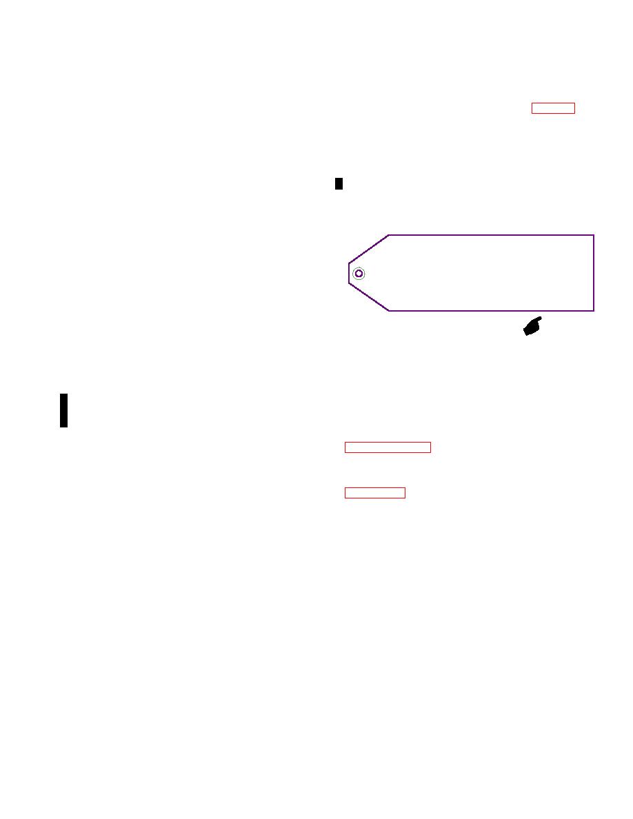
(3) A preservation limit tag (fig. 210) will
a. Preservation. Apply corrosion preven-
be prepared on shipping tag (D25),
tive compound (D4) to bare metal sur-
waterproofed, and secured to helicop-
faces of each equipment item to be trans-
ter airframe a duplicate tag will be at-
ported with helicopters or on other
tached to and stowed with helicopter
designated carrier.
shipping documents.
b. ComponentWrap. Wrap each equip-
(4) Attach a waterproofed DD Form
ment item not mounted on helicopter with
13872, prepared in accordance with
barrier material (D1) sealed with tape
TM 38-250, to fuselage.
(D13).
c. Packaging. Pack wrapped equipment
items in a cleated wood box (D2).
THIS HELICOPTER HAS BEEN PREPARED FOR SHIPMENT ONLY. IT
MUST BE INSPECTED FOR CORROSION EVERY 7 DAYS. IF NOT
NOTE
PREPARED FOR USE IMMEDIATELY AFTER DELIVERY, PLACE HELICOPTER
IN APPROPRIATE STORAGE STATUS PER TM 55-1520-238-23.
Helicopters and components will be
marked in accordance with MIL-STD-129
before loading for shipment.
a. Removed Parts. Each removed compo-
M05-035B
nent will be tagged or marked to indicate
serial number of helicopter from which it
was removed.
b. Separately Loaded Components and
Equipment. The sides of each separate-
ly loaded component container will be
214 HELICOPTER LOADING AND TIEDOWN (C5
marked as follows:
AIRCRAFT SHIPMENT FRONT DOOR LOADING).
(1) Painted oneinch black stripe to indi-
cate center of balance extending three
the loading and tie down of six AH64A helicopters
inches upwards from lower sheathing,
loaded through the front door of a C5 cargo aircraft.
and stenciled oneinch high letters
The loaded configuration of the C5 aircraft is shown in
``CENTER OF BALANCE'', next to
figure FO1.
painted stripe.
Force
Responsibilities
During
(2) Stenciled oneinch high letters, ``SHIP-
Loading. The C5 cargo aircraft loadmaster is
PING WEIGHT'', followed by numerals
responsible for:
indicating shipping weight.
a. Technical direction of all aspects of loading
c. Components and Equipment Requiring
and tiedown.
Special Handling. Shipments contain-
ing hazardous, dangerous, or other materi-
b. Operation of C5 aircraft integral loading
als requiring special handling will be la-
devices (snatch blocks, winch, aircraft cargo ramps,
beled and marked as follows:
etc).
(1) Special handling instructions, marking,
c. Configuration of C5 cargo aircraft.
and warnings will be provided in accor-
(1) Airplane in forward kneeled position.
dance with TM 38-250.
(2) Forward loading doors in drivein load-
(2) A DD Form 1387-2 will be completed
ing position.
and secured to helicopter airframe and
each applicable component container.
(3) Stow flight station ladder.
d. Helicopter Airframe. Each airframe will
(4) Install cargo winch in aft ramp.
be marked and tagged as follows:
(5) Extend troop compartment ladder.
(1) Fuselage will be marked on both sides
to indicate centers of balance location.
d. Direct placement of shoring.
Change 1
|
|
Privacy Statement - Press Release - Copyright Information. - Contact Us |
