 |
|||
|
|
|||
|
Page Title:
Remove Two Tail Rotor Blades (Helicopters Number One, Three, and Five Only). |
|
||
| ||||||||||
|
|
 TM 55-1520-238-S
(2) Reinstall tail rotor blade bolt and nut in
NOTE
tail rotor blade.
This numbering sequence will be main-
tained throughout this section.
(3) Cap or wrap deicing connectors with
barrier material (D1) sealed with tape
Number helicopters one thru six in sequence they are to
(D13).
be loaded through front door of a C5 (FO1). Helicop-
ter number one will be loaded first, followed by helicop-
(4) Coat bare metal of tail rotor hub sur-
ter number two. Helicopter number six will be loaded
faces with corrosion preventive com-
last.
pound (D4).
(5) Wrap disconnected pitch links with
ters Number One, Three, and Five Only).
cushioning material (D5) secured with
tape (D13). Secure wrapped links to
tail rotor hub with tape (D13).
CAUTION
(6) Wrap each tail rotor blade hub fitting
area with barrier material (D1) sealed
Prior to removal of tail rotor blades en-
with tape (D13).
sure that main rotor head and tail rotor
are positioned as required in para-
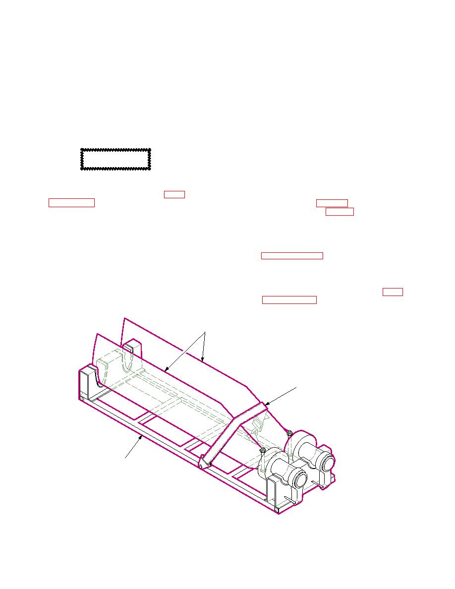
(7) Install two tail rotor blades in blade sup-
port (item 4, table 21) and secure with
loading.
tie down strap (fig. 27).
b. Remove Two Lower Tail Rotor Blades
NOTE
From
Helicopter
Number
Prior to removal of tail rotor blades ensure
Three. TM 1-1520-238-23. Prepare tail
that they are properly color coded and
rotor hub and blades in accordance with
marked with aircraft number.
a. Remove Two Upper Tail Rotor Blades
c. Remove Two Upper Tail Rotor Blades
From
Helicopter
Number
From
Helicopter
Number
One. TM 1-1520-238-23.
Five. TM 1-1520-238-23. Prepare tail ro-
(1) Reinstall pitch link bolt, nut, and wash-
tor hub and blades in accordance with para-
ers in pitch horn
TAIL ROTOR BLADES
TIE DOWN STRAP
SUPPORT
M05-038D
|
|
Privacy Statement - Press Release - Copyright Information. - Contact Us |