 |
|||
|
|
|||
|
Page Title:
Remove Main Rotor Blades. |
|
||
| ||||||||||
|
|
 TM 55-1520-238-S
d. Preservation. Thoroughly coat blade
c. ComponentWrap. Wrap each launcher
root fitting bolt holes with corrosion preven-
with barrier material (D1) sealed with tape
tive compound (D4). Wrap each blade
(D13).
root area with barrier material (D1). Seal
d. Packaging. Pack each removed and
with tape (D13).
wrapped rocket launcher in its shipping
e. Install Blades. Install blades in blade
container (item 36, table 21).
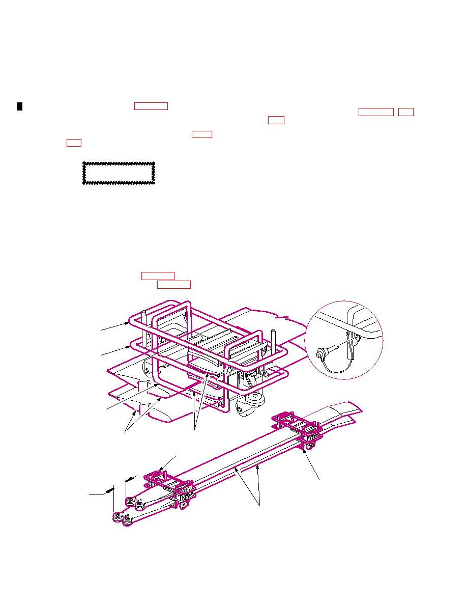
211.3 Remove Main Rotor Blades.
(1) Remove upper and intermediate racks
a. Install droop stop wedges (item 16, table
from blade root and blade tip racks.
(2) Install first blade in lower blade root and
lower blade tip racks.
(3) Place intermediate racks on top of
CAUTION
blade.
(4) Place second blade on intermediate
Prior to removal of main rotor blades,
racks with blade root of second blade
ensure that they are properly marked
inset approximately six inches from first
with aircraft number and appropriate
blade root.
location color code.
(5) Install upper racks on blade root and
blade tip racks.
b. Disconnect Deicing Receptacle.
Disconnect and cap deicing receptacle.
(6) Repeat steps (1) thru (5) for third and
forth blades.
c. Remove Rotor Blades. Remove main
f. Remove Wedges. Remove droop stop
rotor blades (TM 1-1520-238-23.) using
wedges for use on next helicopter to be
crane truck (item 13, table 21) and main
prepared.
rotor blade sling (item 14, table 21).
UPPER FRAME
CENTER FRAME
LOWER FRAME
PADS
MAIN
ROTOR BLADES
BLADE ROOT RACK
FRAME ASSEMBLY
BLADE TIP RACK
FRAME ASSEMBLY
6 IN.
MAIN
ROTOR BLADES
M05-006C
Change 1
|
|
Privacy Statement - Press Release - Copyright Information. - Contact Us |