 |
|||
|
|
|||
|
|
|||
| ||||||||||
|
|
 TM 5-6675-250-34
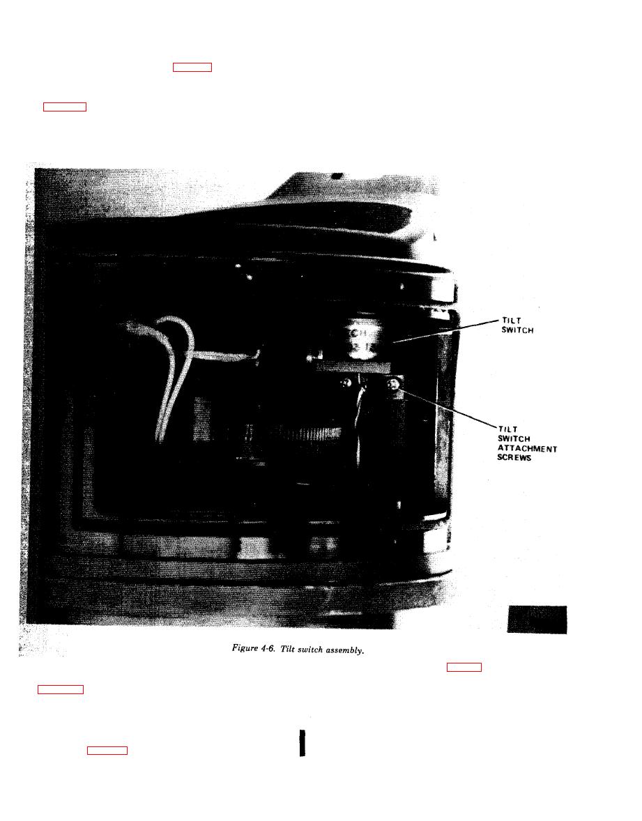
4-8. Tilt Switch Assembly (fig. 4-6)
tachment screws and remove the assembly from the
housing.
a. Removal.
(1) Remove the gearbox assembly, refer to
b. Inspection.
(para 4-5a).
(1) Check for bent or missing pins.
(2) Unsolder and disconnect the lead wires from
( 2 ) Visually inspect for burned surfaces.
t h e tilt switch terminals.
(3) Check for shorts between the pins and
(3) Remove the two tilt switch assembly at-
housing.
c . Installation.
(1) Prepare the two attachment screws per
a. R e m o v a l .
( 1 ) Remove ten attachment screws and remove
(2) Place the tilt switch assembly in the housing
the main connector housing cover containing the
a n d secure with
the two attachment screws.
t i m e totalizing meter from the housing. The cover
( 3 ) Connect
and solder the leads.
shall remain connected to the housing by the leads to
(4) Replace
the gearbox assembly and cover,
1A1J1.
refefer to (para
4-5b).
4 - 1 0 , Change 1
|
|
Privacy Statement - Press Release - Copyright Information. - Contact Us |