 |
|||
|
|
|||
|
Page Title:
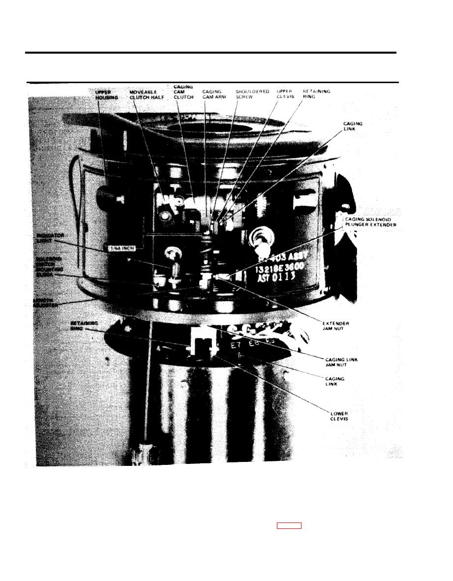
Figure 2-78. Caging Mechanism adjustment. |
|
||
| ||||||||||
|
|
 TM 5-6675-250-34
Table 2-1. Troubleshooting - Continued
MALFUNCTION
TEST OR INSPECTION
CORRECTIVE ACTION
e. Connect the GRU to the ECU and apply power in the BIAS mode.
f. Rotate the cage-uncage knob until the caging arm passes over center of the caging link. At the point where the arm
crosses over center, observe that a small gap (approximately 1/64 inch) is present between the head
of the shoulder screw and the upper clevis.
g. If the gap described in step (f) is not correct, rotate the length adjuster counterclockwise to increase
the gap and clockwise to decrease the gap.
h. Continue rotating the cage-uncage knob until the caging arm guide pin (fig 2-80) moves about 1/32 inch
in the guide clot. The uncaged indicator should light at that point. If the indictor does not light
at the proper point, the caging control switches need adjusting.
2-64
|
|
Privacy Statement - Press Release - Copyright Information. - Contact Us |