 |
|||
|
|
|||
|
Page Title:
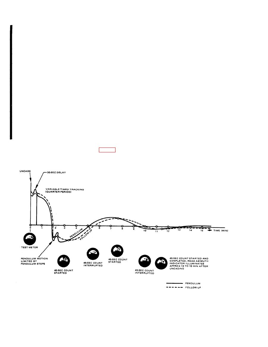
Figure 1-8. Pendulum and follow-up relationship. |
|
||
| ||||||||||
|
|
 TM 5-6675-250-34
train is shifted to high speed to permit the follow-up
(4) GC. Placing the MODE SELECT switch
assembly to follow the pendulum from large offsets
to GC begins the gyro-compassing operation.
from north. The duration of the tracking operation
Through 2A2S3A-5, 400 Hz power form the 26 Vac
corresponds to the setting of the LATITUDE switch
bus is distributed to the primary of 2A2T2, the time
and is approximately equal to one quarter of the
totalizing meter, and relay 2AK4A-1. Through
pendulous period. After the variable timed track-
2A2S3B-5, B voltage is applied to 2A1K4B-4, the
ing, the servo gear train is shifted to slow speed. The
control winding of the gyro motor, and to the high
meridian-seeking action of the pendulum is reflec-
side of the speed changer. 400 Hz power is applied to
ted in its relation to the follow-up assembly. When
the gyro motor through the primary of transformer
the pendulum and the follow-up assembly are align-
2A2T2 and the closed contact 2A2K1A. The gyro
ed, the servo motor drive signal is removed. When
sync sensor circuit monitors voltage at the second-
the servo motor drive signal is off for a 45- second
ary of 2A2T2 and determines when the synchronous
period, indicating stable alignments, the READ AZ-
speed is reached, the GYRO SYNC indicator illu-
IMUTH indicator illuminates, the servo loop is in-
minates and relay 2A1K4 becomes energized. Ener-
terrupted, and the theodolite lamps illuminate.
gizing 2A1K4 converts the 400 Hz signal to regu-
Through the 45-second delay circuit, gyro-corn-
lated 26 Vat, and energizes the uncaging solenoid.
passing is continued when the RESET switch is
Through 2A1K4A, 400 Hz is applied to the high side
pressed. The counting operation of the delay circuit
of the motor/tach windings.
is restarted and another 45 seconds (minimum) is
(a) When the GYRO SYNC indicator illu-
required to obtain a READ AZIMUTH indication.
minates the pendulum is to be uncaged. Uncaging
The reset operation verifies the validity of the ini-
the pendulum energizes relay 2A1K3 to complete
tial indication. With the READ AZIMUTH indi-
the servo loop and initiate a timing operation. Ini-
tial pendulum energy is dissipated during a 30-sec-
cator illuminated, azimuth is determined through
ond damping period following uncaging (fig. 1-8).
theodolite readings.
After the 30-second damping period, the servo gear
1-10, Change 1
|
|
Privacy Statement - Press Release - Copyright Information. - Contact Us |