 |
|||
|
|
|||
|
Page Title:
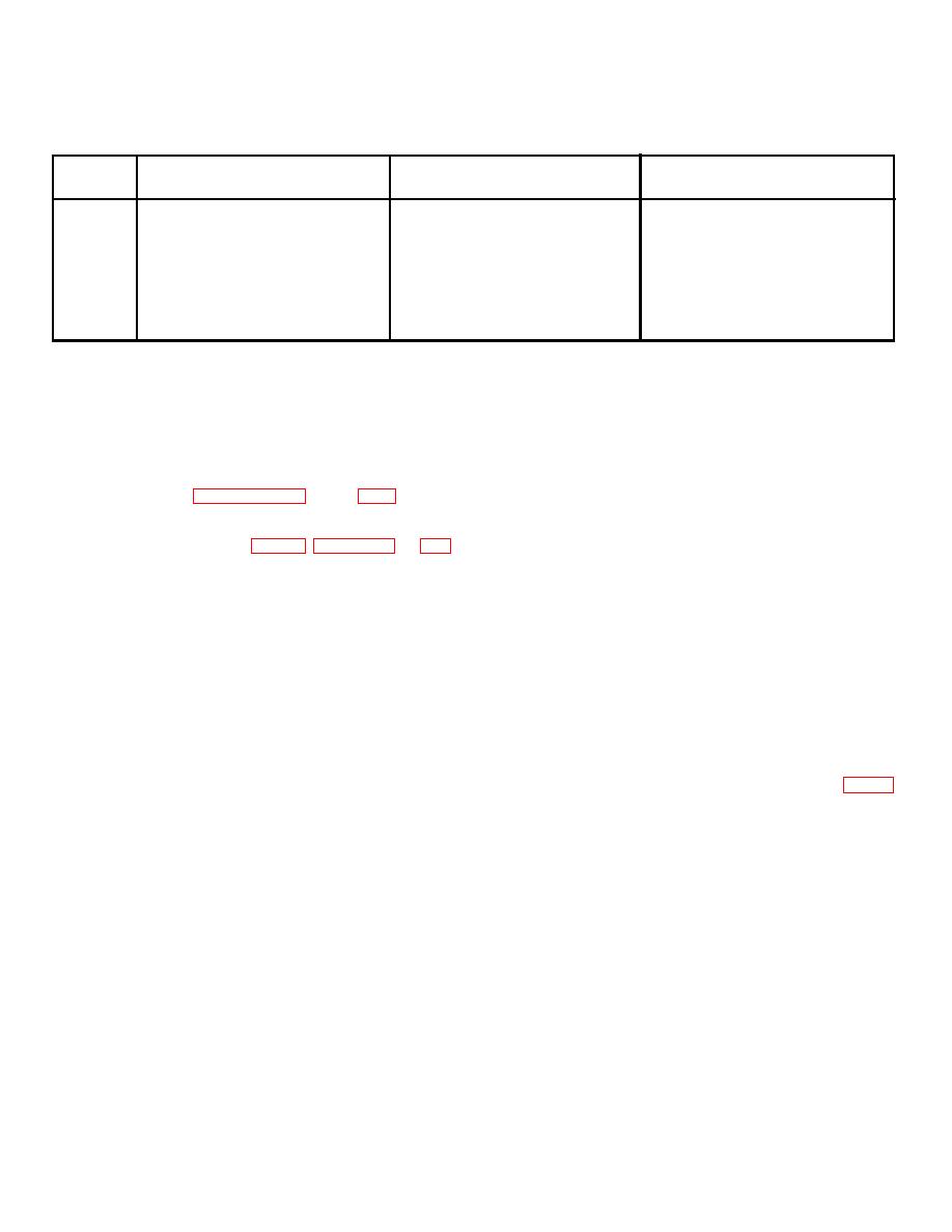
Chart 7-1. Troubleshooting Chart - Continued |
|
||
| ||||||||||
|
|
 TM 5-6350-262-14/5
NAVELEX 0967-LP-466-9052
TO 31S9-4-38-1 Chg 2
Chart 7-1. Troubleshooting Chart--Continued
Step
Procedure
Symptom
Probable Trouble
Corrective Action
12c
a. Meter indicates 0 V dc.
a. Defective operating mode switch
a. Replace switch.
S3.
12d
a. Meter still indicates less than 1 V
a. Defective operating mode switch
a. Replace switch.
dc after expiration of entrance time
S3.
delay.
13a
a. Meter indicates less than infinite
a. Defective transmitter resync switch
a. Replace switch.
S2.
13b
a. Meter indicates more than 1 ohm.
a. Defective transmitter resync switch
a. Replace switch
S2.
(8)
All attaching and mounting hardware for
b. The information in this section supplements that in
rightness.
section III (troubleshooting) and provides instructions for
correcting malfunctions detected during visual inspection and
b. Cleaning. Use a mild solution of warm water and
performance testing, and for adjusting the entrance and exit
liquid soap to clean exterior surfaces. After cleaning rinse
time delay functions.
parts with cold water to remove any soap solution and dry
thoroughly. Use a soft camel's-hair brush or vacuum cleaner
c. Repair of the control unit will normally consist of on-
with suitable attachment to remove accumulated dust from
site replacement of defective components and modular
components within the control unit enclosure.
assemblies in order to get the J-SIIDS back into service as
quickly as possible. Paragraphs 7-9 through 7-21 provide
c. Repair Precautions.
Use standard maintenance
removal and replacement procedures for those items requiring
practices and observe the following precautions:
instructions in addition to the disassembly sequence shown in
(1) Use exact replacement parts. A part with the
the equipment exploded view (fig. C-1). Figures 7-1 and 7-2
same electrical value or function but different physical size
show the component interconnecting wiring.
may cause trouble.
NOTE
(2) Soldering irons of less than 50 watts should
Whenever a repair procedure requires
be used to solder this equipment. Overheating of some parts
turning off the control unit power,
may cause damage.
Audible Alarm BZ204( )/FSS-9(V) must
7-9. AC Power Lamp Bulb Replacement
first be disabled to prevent sounding an
a. Unscrew and remove white lens.
alarm.
b. Push in and turn bulb 1/8 turn counterclockwise.
7-8. General Maintenance Instructions
Remove bulb.
a. In-Process Inspection. During repair, inspect control
c. Install new bulb.
unit after removal of parts for defects not visible when the unit
d. Install white lens.
is assembled. Continue the inspection during assembly to
7-10. Status Processor PWB Assembly Replacement
insure that parts are properly assembled and that the unit will
meet performance standards. During the repair process,
a. Removal. Status processor printed wiring board
inspect the control unit for the following:
assemblies Al through All (25, 26, 27, 28, 29, and 31, fig. C-
1) are easily removed by lifting up the inboard end of the
(1) Components for cleanliness.
ejector mechanism with the index finger and using it as a lever
(2) Painted surfaces for deterioration or
to lift the board out of the receptacle. Considerable force may
scratches.
be required to disengage the tight connection between board
(3) Screws for damage or corroded threads.
and receptacle. Printed wiring board assembly A12 (30)
(4) Nuts and screw holes to insure they are not
simply plugs onto the All assembly (31).
stripped.
b. Installation. Each printed wiring board assembly (Al
(5) Components for breaks, chips, or cracks.
through All) is identified by the number appearing in the
(6) Moving parts for wear.
corner opposite the ejector mechanism.
Corresponding
numbers appear across the bottom of the status processor
(7) Electrical wiring for fraying or other damage.
chassis to provide proper location of printed
Change 2 7-6
|
|
Privacy Statement - Press Release - Copyright Information. - Contact Us |
