 |
|||
|
|
|||
|
Page Title:
Chart 7-1. TROUBLESHOOTING CHART |
|
||
| ||||||||||
|
|
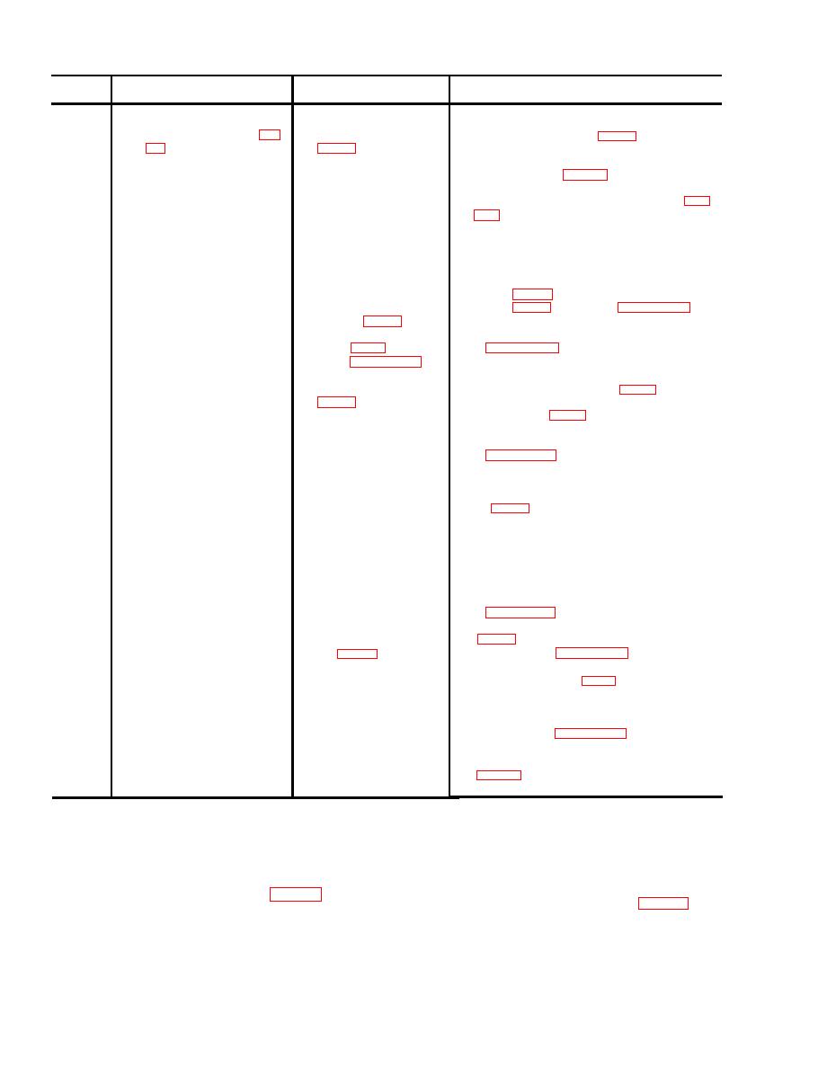 Chart 7-1. TROUBLESHOOTING CHART
Step
Procedure
Symptom
Corrective measures
Constant alarm condition even
a. If voltage is below tolerance disconnect leads from
1
a. Check for 20 2 Vdc at
with all GAIN controls (fig.
terminal 7 and 8 of TBl
terminals 7 and 8 of TB1 (fig. 1-1) and measure the
1-1) turned down to 1.
voltage level from the source.
b. If voltage is still below tolerance check inter-
connecting wiring (para 7-7).
c. If voltage is normal replace processor PC board with
a spare and check the processor and receiver (para
b . If operating in conjunc-
a. If no SYNC pulse is present refer to TM 5-6350-
tion with a processor/
262-14/14.
transceiver
ultrasonic motion signal,
b. If SYNC pulse is present. replace the processor PC
verify the presence of
board with a spare and reset the receiver GAIN
1 .2V rms SYNC pulse
control (fig. 1-1) and the processor SENSITIVITY
between terminals 7 and
control (fig. 1-1) as outlined in paragraph 2-8.
2 of TB1 (fig. 1-1).
Replace the faulty PC board and repeat procedures
c. Check the tamper
switches (fig. 1-1) as out-
lined in paragraph 2-14 a.
2
Poor sensitivity at all
a. Check for 5.3 .5Vdc at
a. If voltage is low or zero, disconnect the leads
receivers.
terminals 1 and 2 of TB2
from terminals 1 and 2 of TB2 (fig. 1-1 ) and
check the voltage at the processor terminal
1 and 2 of TB2 (fig. 1-1 ).
b. If the voltage is normal (5.3 .2Vdc) check the
interconnecting wires according to procedures
in parallel. Therefore a multimeter connected to the
leads removed from terminals 1 and 2 of TB2 (re-
ceiver, fig. 1-1) should read a finite resistance for one
polarity, and a resistance approximately 30 times
higher for the opposite polarity. A low resistance ob-
served for both polarities indicates a short in the sys-
tem requiring sequential disconnection of the re-
ceivers to isolate the problem.
c . If the voltage is still low replace the processor PC
board with a spare one and perform procedures
3
Poor sensitivity at one
a . If the voltage is normal at terminal 1 and 2 of TB1
a. Check for 5.3 + .2 Vdc
receiver.
at terminals 1 and 2 of
the procedures in paragraph 2-8.
TB1 (fig. 1-1) in the
faulty receiver.
b . If the voltage is low, disconnect the leads from
terminals 1 and 2 of TB1 (fig. 1-1) (faulty re-
ceiver) and measure the voltage at the line.
c . If the voltage is normal at the interconnecting
wires, replace the receiver PC board and perform
the procedures in paragraph 2-8.
d . If the voltage is still low, check the interconnect-
ing wires for a short circuit or low resistance
Section IV. MAINTENANCE
7-9. Removal and Replacement Proce-
(3) Remove and retain the seven 6-32 x 3/8 inch
long screws fastening the PC board to the enclosure
dures
interior. Remove the PC board.
a.
(1) Remove and retain the two 6-32 x 3/8 inch
(1) Orient the PC board so that the terminal
long screws fastening the cover to the enclosure.
boards (TB1 and TB2) are adjacent to the conduit
(2) Tag, identify, and remove the leads from
entrance. Secure the PC board to the enclosure using
terminal boards TB1 and TB2.
seven 6-32 x 3/8 inch long screws.
7-4
|
|
Privacy Statement - Press Release - Copyright Information. - Contact Us |
