 |
|||
|
|
|||
|
Page Title:
Figure 2-2. Processor connection methods. |
|
||
| ||||||||||
|
|
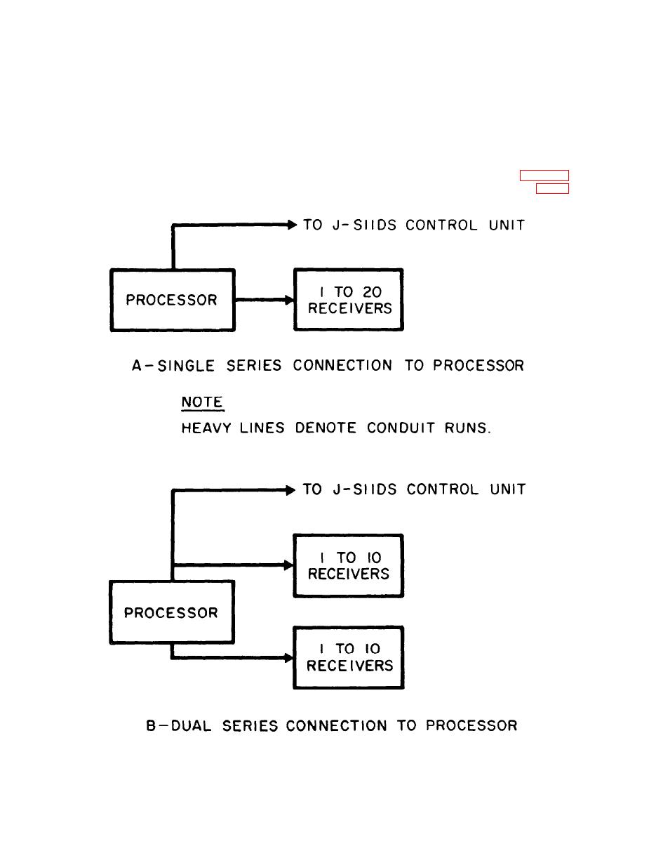 b. Large areas greater than 15 by 20 feet or a
ting maximum protection).
multiple number of rooms can be protected using one
processor with anywhere from one to twenty
d. The processor shall be located with in the
receivers connected by cable up to a length of 500
protected area. It should be protected from the
feet.
weather, mounted in a horizontal or vertical position
c. Mounting surfaces for the receiver should be
and firmly secured. To facilitate interconnections
sturdy and free from vibration. The receiver may be
and maintenance, consideration should be given to
mounted at a 0 degree, 45 degree, or 90 degree plane
its accessability and to the adjacent approaches to
from the surface thus permitting any major angle
the unit. Placement of the processor must be within
within 180 degrees. The selected location should also
500 feet of the receivers and may be located at either
be viewed from the interconnection standpoint as
end of a string: of receivers as shown in A of figure 2-2
or located between receivers as shown in B of figure
well as to facilitate access for maintenance purposes
2-2.
(these conditions are secondary to locations permit-
Figure 2-2. Processor connection methods.
ME 6350-262-14/2/2-2
2-2
|
|
Privacy Statement - Press Release - Copyright Information. - Contact Us |
