 |
|||
|
|
|||
|
Page Title:
CHAPTER 2 SERVICE UPON RECEIPT AND INSTALLATION |
|
||
| ||||||||||
|
|
 CHAPTER 2
SERVICE UPON RECEIPT AND INSTALLATION
Section I. EQUIPMENT PLANNING
2-1. General
2-2. Equipment Capabilities
Equipment planning involves becoming familial
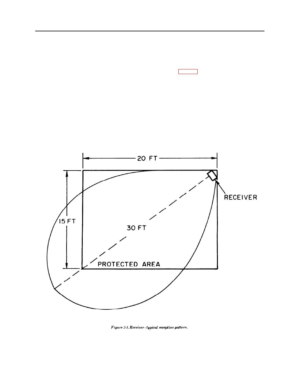
1. Each receiver is capable of covering an area of 15
with the capabilities of the processor and the
by 20 feet when mounted at the corner of the
receiver used to detect ultrasonic energy generated
rectangle (fig. 2-1). The reception beam pattern
during attempts at forced penetration. One proces-
extends at 90 degrees and approximates an
sor is capable of operating with one to twenty
eggshape, with maximum sensitivity perpendicular
receivers. To determine the number and the place-
to the unit cover. For positive protection, the selected
ment of the receivers, requires an investigation of
mounting location of the receiver must have direct
the size of the area, places within the area that are
line of sight to the area being protected and it is
most likely location of forced penetration, and logical
desirable to minimize the distance.
positions and angles for mounting the receivers.
NOTE
Detection is independent of distance, and depends only on the
intensity of the signal. For maximum protection the distance
NOTE
between the receiver and most likely site of forced entry should be
The following installation procedure must be made with
minimized and preferably should be in a line perpendicular to the
the assistance of direct support (intermediate or higher
receiver cover
level maintenance personnel.
ME 6350-262-14/2/2-1
2-1
|
|
Privacy Statement - Press Release - Copyright Information. - Contact Us |