 |
|||
|
|
|||
|
Page Title:
Figure 5-1. Transmitter code plug orientation. |
|
||
| ||||||||||
|
|
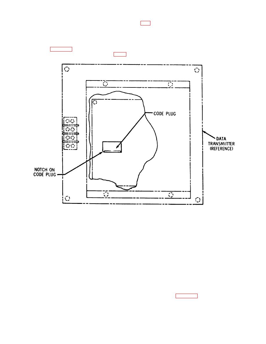 code plug in the transmitter and the
(b) Install cover on transmitter using the as
code plug in the receiver are identical
shown in figure screws and lockwashers (items 2 and 3
with
respect
to
identification
of C-1) provided.
numbers. The new code plug must be
installed with the notch oriented as
shown in figure 5-1.
(a) Install new code plug as shown in figure
ME 6350-262-14112/5-1
Figure 5-1. Transmitter code plug orientation.
b. Receiver.
(2) Installation. Follow these steps to install the
(1) Removal. Follow these steps to remove the
code plug in the receiver:
receiver code plug:
NOTE
(a) Remove four (4) screws (item 2 of C-2)
The identification numbers of the
from transmitter and receiver must always be identical
code plugs in the transmitter and
receiver assembly.
receiver must always be identical.
(b) Remove ten (10) screws (item 3 of C-2)
Use extreme care to assure that the
holding cover on receiver and remove cover.
code plug in the transmitter and the
(c) Remove code plug (item 4 of C-1) from
code plug in the receiver are identical
receiver.
within
respect
to
identification
numbers. The new code plug must be
installed with the notch oriented as
shown in figure 5-2.
5-2
|
|
Privacy Statement - Press Release - Copyright Information. - Contact Us |
