 |
|||
|
|
|||
|
|
|||
| ||||||||||
|
|
 corridor. The number of transceivers installed to cover
2-5. Transceiver Placement
a given area or number of rooms can be calculated by
the graphs in figures 2-1 and 2-2. These graphs relate
Placement of transceivers is extremely important for
the typical maximum range for each transceiver to the
optimum surveillance protection. Transceivers should
number of transceivers in the system and levels of the
be placed so that the most likely intruder motions (such
background turbulence.
as through a doorway or along a corridor) are toward, or
away from the transceiver, rather than across the beam.
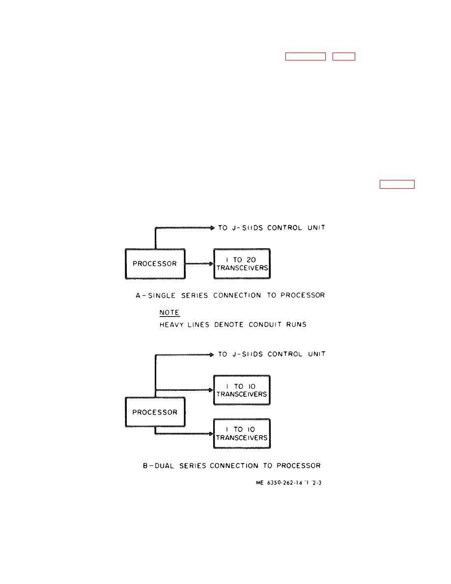
2-6. Processor Placement
If more than one transceiver is necessary to protect an
area, it is preferable to have them all face in one
The processor shall preferably be installed within the
direction so that they may reinforce one another. For
protected area. It should be placed in a weather
example, to protect a long hall (less than 100 feet), do
protected area, mounted in a horizontal or vertical
not place transceivers at each end so that they face
position, and firmly secured.
To facilitate
each other. Instead, place one transceiver at one end
interconnections and maintenance, consideration should
and the second transceiver at the mid point, also facing
be given to its accessibility and to the adjacent
in the same direction. An alternate would be two
approaches to the unit. Placement of the processor in
transceivers placed in the center of the hallway pointing
relation to the transceivers may be located at either end
in opposite directions. An exception to this rule is when
of a string of transceivers as shown in A of figure 2-3, or
the corridor is more than 100 feet long. Transceivers
located between transceivers as shown in B of figure 2-
may then be placed at each end facing each other. In
3.
this configuration it must be recognized that coverage
will be pool. or non-existent at the mid-area of the
Figure 2-3. Processor-connection methods.
2-3
|
|
Privacy Statement - Press Release - Copyright Information. - Contact Us |
