 |
|||
|
|
|||
|
|
|||
| ||||||||||
|
|
 e. Continue the drying until four consecutive samples
taken from both the top and bottom. To determine the
drying progress, plot curves of load current, top liquid
test at least 26 K V and preferably 30 K V or higher and
temperature, and dielectric strength versus time. A
until a satisfactory "cloud test" is obtained as outlined in
decrease in dielectric strength indicates that moisture is
passing from the winding and insulation into the insulating
f When the drying operation has been completed, the
oil. As the moisture is driven out of the oil, the dielectric
liquid removed for sampling must be replaced. To avoid
strength will increase, indicating that the drying process is
the possibility of entrapping air bubbles in the windings, it
progressing satisfactorily.
is recommended that the oil be returned through the
upper filter press connection.
Section II. INSULATOR REPAIR
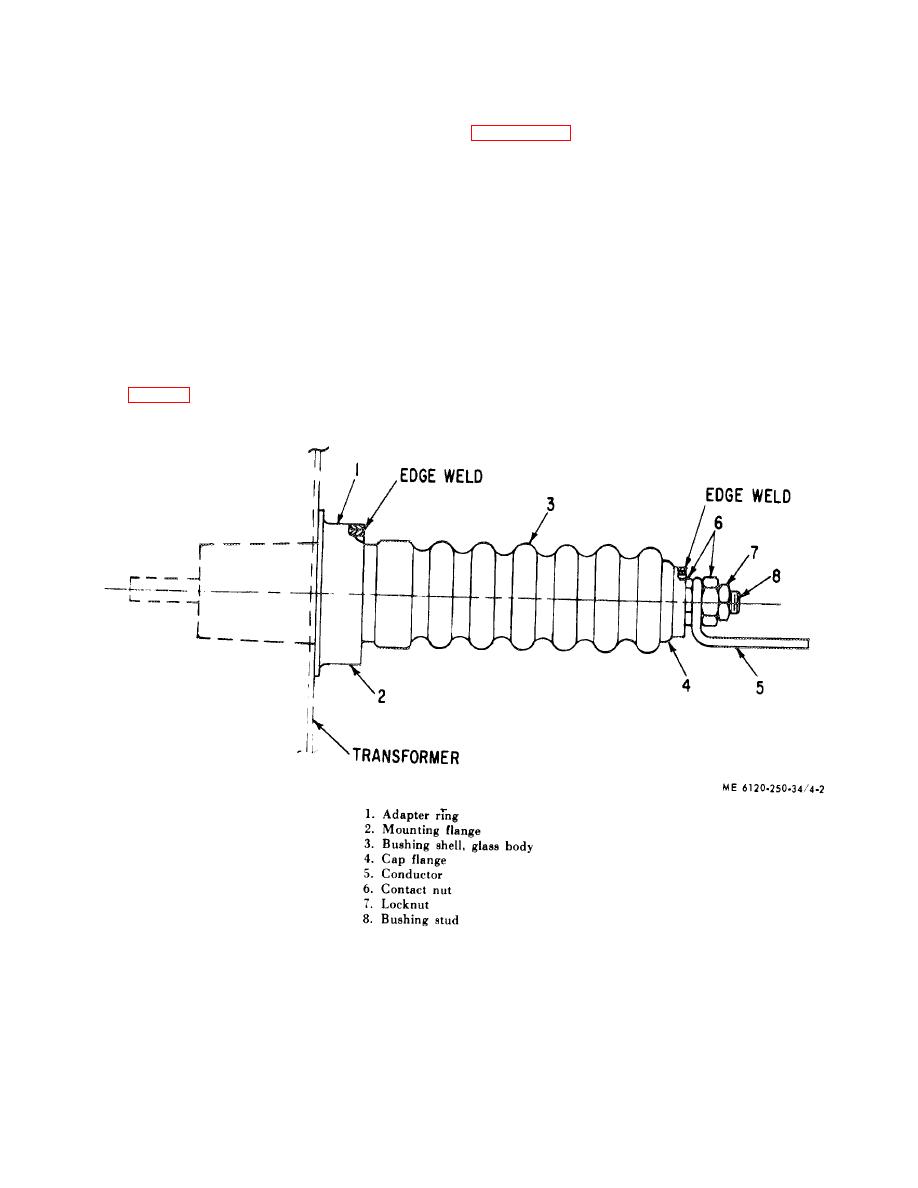
4-6 General
thermal coefficient of expansion designed to match that of
the metal. The cap flange is fusion-welded to a spinning
High and low-voltage winding leads are brought out
brazed on the bushing stud. The mounting flag is fusion-
through hermetically sealed RE-X glass ceramic
welded to an adapter ring 11 ) which in turn is welded to
bushings. A metal-to-glass seal is established in the
the transformer tank wall, thus completing the bushing
bushing through the use of an oxide treatment of the cap
seal without the use of gaskets.
flange (4, fig. 4-2) and mounting flange (2) prior to
casting, plus a special glass ceramic material having a
Figure 4-2. Transformer RE-X bushing.
4-7. Removing Insulator Bushing.
CAUTION
a. Lower the insulating oil until the level is below the
Before attempting to remove or replace a bushing,
lowest insulator bushing.
thoroughly flush out the air
4-3
|
|
Privacy Statement - Press Release - Copyright Information. - Contact Us |