 |
|||
|
|
|||
|
Page Title:
Figure 2-15. Lifting and jacking methods for low voltage section. |
|
||
| ||||||||||
|
|
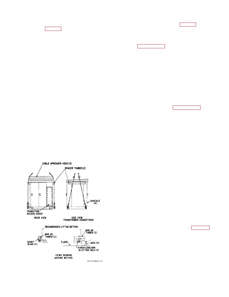 side of lifting lug. This should form a short lifting sling
2-20. Low Voltage Section Installation
whose loops are around the six inch long rod, one each
a. Lifting Low Voltage Section, (fig. 2-15).
side of lifting lug. (fig. 2-15.)
(1) Clear trailer deck of all unnecessary
(6) Repeat steps (4) and (5) on all four corners.
equipment, and have area for low voltage section
(7) Place a bar (or timber) across each end of
clear.
low voltage cabinet. Insert ends in sling loops of front and
(2) Attach slings, and lifting devices, and lift
rear corners.
cabinet per paragraph 2-19c.
(8) Place one lifting jack under bar or timber at
(3) With hoist move cabinet into position for
each lifting lug.
lowering onto trailer. The transition side goes toward the
CAUTION
transformer.
Inspect and make sure all panels and doors
CAUTION
are closed and secured. If circuit breakers
Care must be taken not to hit the transformer bus
are in they should be in the full "IN" position
connections when lowering low voltage section on
and open.
trailer.
(4) Lower cabinet slowly and guide it to its
position as close as lifting equipment will allow.
(9) Using lifting jacks raise cabinet a sufficient
(5) When cabinet is on trailer deck, remove
height to clear rollers to be used. Raise cabinet as evenly
lifting equipment from cabinet and area.
as possible so not to twist and distort it, causing damage
b. Connecting Low Voltage Section to Transformer.
to equipment.
(10) Place construction rollers under the three
(1) If cabinet must be moved more than a few
channels of the cabinet base.
inches, the method described in paragraph 2-19d may be
used.
(2) Install gasket on flange of the transition of
CAUTION
low voltage cabinet as follows:
(a) Clean flange surface.
The rollers must be long enough to fit the
(b) Apply a thin coat of adhesive to both
entire width of the three bottom channels
the flange and one side of gasket.
and placed so that the cabinet is not
(c)
Allow adhesive to dry until it is no
distorted. Otherwise serious damage may
longer tacky.
result to the equipment.
(d) Install gasket just outside the mounting
(11 ) Lower cabinet onto construction rollers.
bolt holes of the flange. Allow the piece across the top to
(12) Cabinet may be shifted or moved using the
overlap the two side pieces. Press gasket against flange
rollers.
with enough pressure to make good contact.
(3) Move cabinet into position. The bolt holes in
base must be aligned with holes in trailer deck. The bolt
holes in flange must line up with holes in flange of
transformer.
NOTE
If trouble is experienced with aligning flange
holes, it may be possible to line them up by
loosening trans- former mounting bolts. Then
when flange holes line up insert bolts and hand
tighten nuts. Then line low voltage section base
holes with trailer holes and insert low voltage
section mounting bolts and nuts.
(4) With all bolts inserted in flange and
mounting base, tighten flange bolts and then mounting
bolts to the torque of the bolt size in table 1-1. If
transformer had been loosened be sure to retighten.
(5) On the right rear of cabinet loosen and
remove the 24 bolts and washers securing the access
cover on the transition area, between transformer and low
voltage cabinet.
Figure 2-15. Lifting and jacking methods for low voltage
section.
2-15
|
|
Privacy Statement - Press Release - Copyright Information. - Contact Us |
