 |
|||
|
|
|||
|
Page Title:
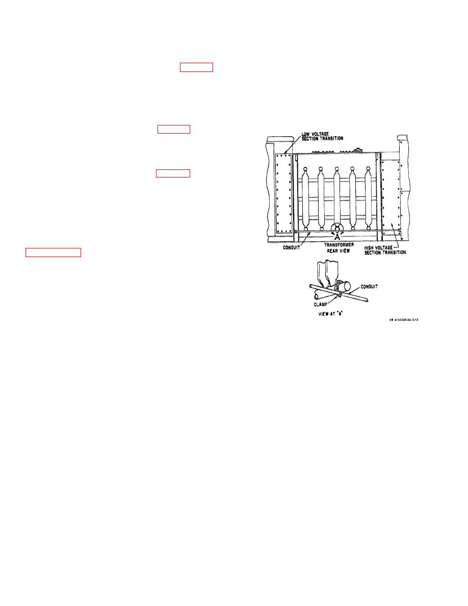
Figure 2-12. Rear view of transformer |
|
||
| ||||||||||
|
|
 (17) Completely cover each connection with I-200
(4) With all bolts inserted in flange and
tape.
mounting base, tighten flange bolts and then mounting
(18) Completely cover each connection with
bolts to the torque of the bolt size in table. If transformer
"Duxseal" type NSG.
had been loosened be sure to retighten. See table 1-1 for
(19) Replace transition front cover and secure it.
correct torque values.
(20) Close and secure upper and lower front
(5) Remove the lower rear panel of the high
panels.
voltage section.
(21) Check and make sure switch is in the "open"
(6) Feed the two wires in the conduit from the
position and bar covering switch operating socket is in
low voltage section through the conduit mounting hole in
place and locked.
high voltage section. This conduit connection is at the
bottom left side looking in from rear. (fig. 2-12).
(7) Connect conduit to high voltage section.
(8) Replace and secure lower rear panel.
(9) Loosen and remove the three bolts securing
the lower front hinged panel. Open panel.
(10) Connect the two wires (fig. 2-13) from the
conduit to the heater terminal board terminals 1 and 2.
The terminal board is located at the bottom left side right
behind the heater. Make sure connections are tight.
(11) Loosen and remove the four bolts securing
the upper front hinged panel. Open panel.
(12) Before connecting load break switch to
transformer check adjustments and alignment to insure
proper operation.
See Checks and Adjustments
(13) Loosen and remove the eighteen bolts
securing the transition front access cover, remove cover.
(fig. 2-101.
(14) Identify each conductor to indicate their
phase relationship with the rest of the system.
(15) Check and make sure each connector of
transformer is clean and apply a coat of contact lubricant.
(16) Connect
switch
conductors
to
the
transformer connector using cables clamps, tighten nut to
approximately 20 ft-lbs.
Figure 2-12. Rear view of transformer.
2-12
|
|
Privacy Statement - Press Release - Copyright Information. - Contact Us |
