 |
|||
|
|
|||
|
|
|||
| ||||||||||
|
|
 2-14. Load Break Switch Installation
a.
General.
Prior to installation of switch,
adjustments and alignment checks should be made to
insure proper operation.
CAUTION
To check operation of load break switch it
must be operated slowly with the power
springs blocked. See TM 5-6120-250-12.
b.
Checks and Adjustments.
(1) Upper(closed) mechanism stop. The
upper buffer stops, (3, fig. 2-3 ) located on either side of
the mechanism at the ends of the main crank shaft, must
be adjusted to position the operating rod cranks when the
switch is closed. Operate the switch to the fully closed
position. The operating rod (8, fig. 2-4! must go over
toggle approximately 1/l inch at the crank connection,
when the switch is closed. A simple means of measuring
the correct toggle angle is to place a straight edge along
the upper side of the operating rod. Extend it until it is
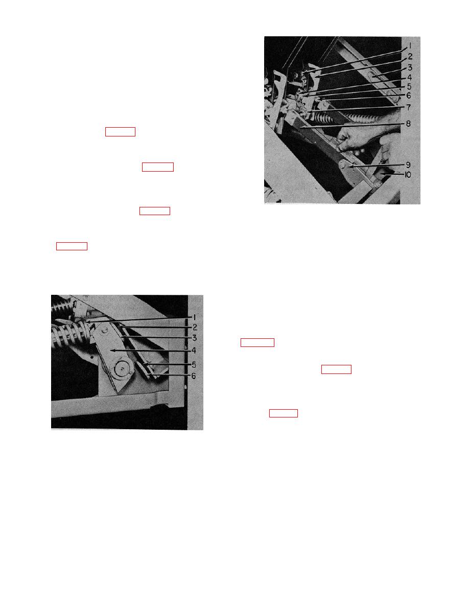
1. Auxiliary blade spring
over the square main shaft (10, fig. 2-4). The dimension
2. Auxiliary blade release hook
from the straight edge to the closest corner of the square
3. Spring stop
shaft should be 1/4 to 3/8 inch. If adjustment of the stop
4. Cramming screw
is necessary, remove the cotter pin holding the spring
5. Lock nut
stop (3, fig. 2-4). Move washers and metal shims from
6. Adjusting nut
the front to the rear or the reverse) until the proper toggle
7. Release hook spring
angle is obtained. Adjust the stops at both ends of the
8. Operating rod
main shaft the same amount to keep them
9. Operating rod crank
10. Main crank shaft
balanced.
Figure 2-4. Switch blade adjustments.
(2) Primary wipe. The operating rod must
fully close the switch primary blades to obtain the correct
primary finger wipe. With the switch in the closed
position, pull the top of the primary contact blades (I 1,
connection clearances. There should be I / 64 to I / 32
inch clearance between the buffer stop 18) and the
primary blade stop (1, fig. 2-6). There should also be 3/
16 to I / 4 inch between the edge of the primary blade and
the front of the primary contact support. Adjust the length
of the rod by use of the adjusting nut (6, fig. 2-41 to
obtain the 3 / 1 6 to I / 4 inch gap then adjust the buffer
stop (8, fig. 2-5) by adding or removing shims to get the I
/ 64 to I /32 inch clearance.
1.
Collar
2.
Buffer rubber
3.
Upper buffer stop
4.
Booster crank
5.
Buffer rubber
6.
Lower buffer stop
Figure 2-3. Buffer assembly, load break switch
2-5
|
|
Privacy Statement - Press Release - Copyright Information. - Contact Us |
