 |
|||
|
|
|||
|
|
|||
| ||||||||||
|
|
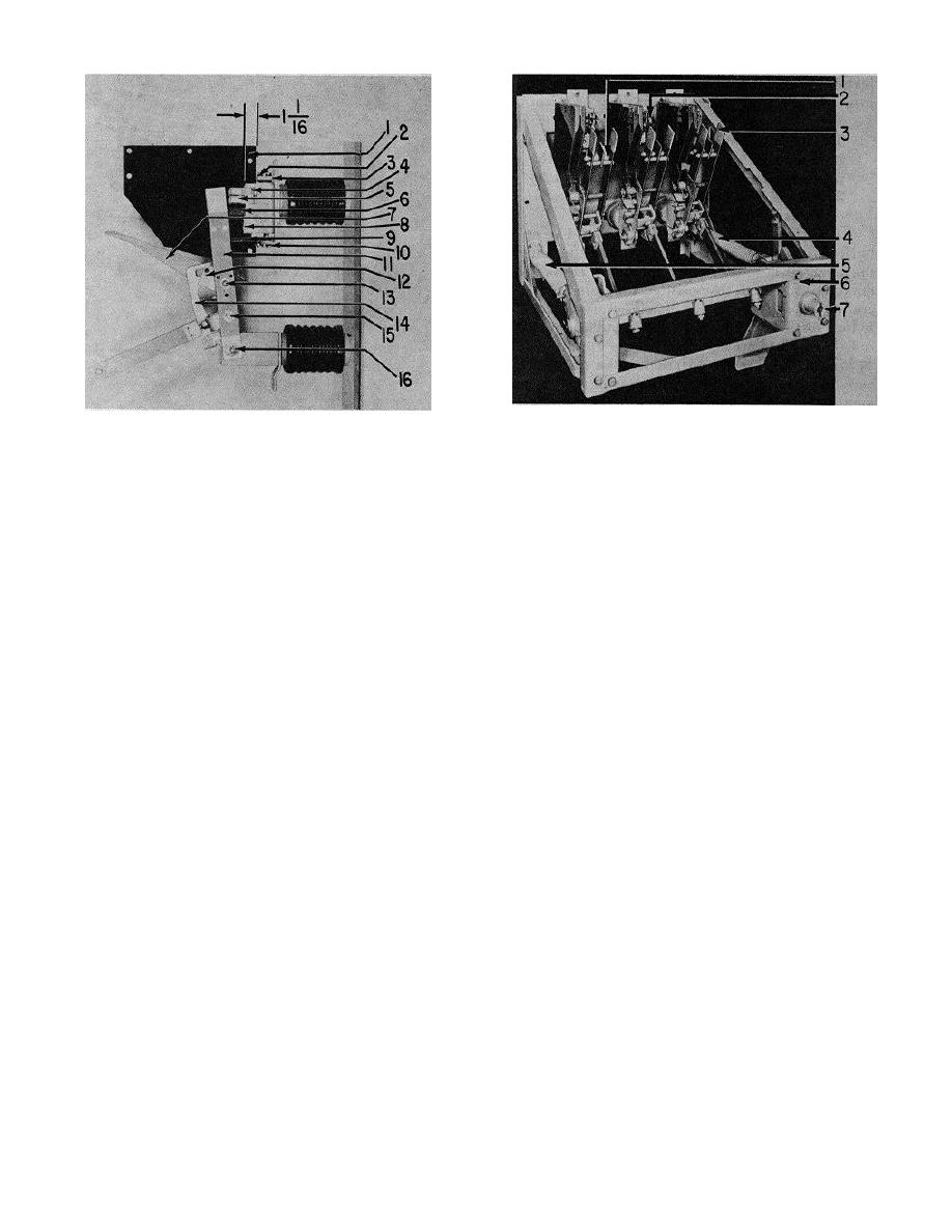 1.
Primary blade buffer stop
1.
Buffer stop
2.
Primary contact fingers
2.
Arc chute mounting bolts
3.
Primary contact blade
3.
Shims
4.
Primary spring
4.
Contact bolt
5.
Booster spring
5.
Primary contact fingers
6.
Operating mechanism
6.
Arcing contact fingers
7.
Operating hub
7.
Auxiliary blade
8.
Buffer stop
Figure 2-6. Switch partially open.
9.
Guide block
10.
Arc chutes mounting bolts
11.
Primary contact blade
(3) Primary gap. The primary gap should
12.
Auxiliary blade release hook
be measured with the primary blades in the normal
13.
Pivot pin for auxiliary blade
position. A measurement should be made from the
14.
Auxiliary blade release hook
primary blade stop or spacer (3, fig. 2-71 to the stationary
15.
Operating rod clevis pin
primary contact 121. The dimension should be I inches
16.
Hinge pin
plus or minus 3 / 8 inch. If this dimension is not correct,
the lower buffer stop (6,
Figure 2-5. Unit pole closing.
2-6
|
|
Privacy Statement - Press Release - Copyright Information. - Contact Us |
