 |
|||
|
|
|||
|
|
|||
| ||||||||||
|
|
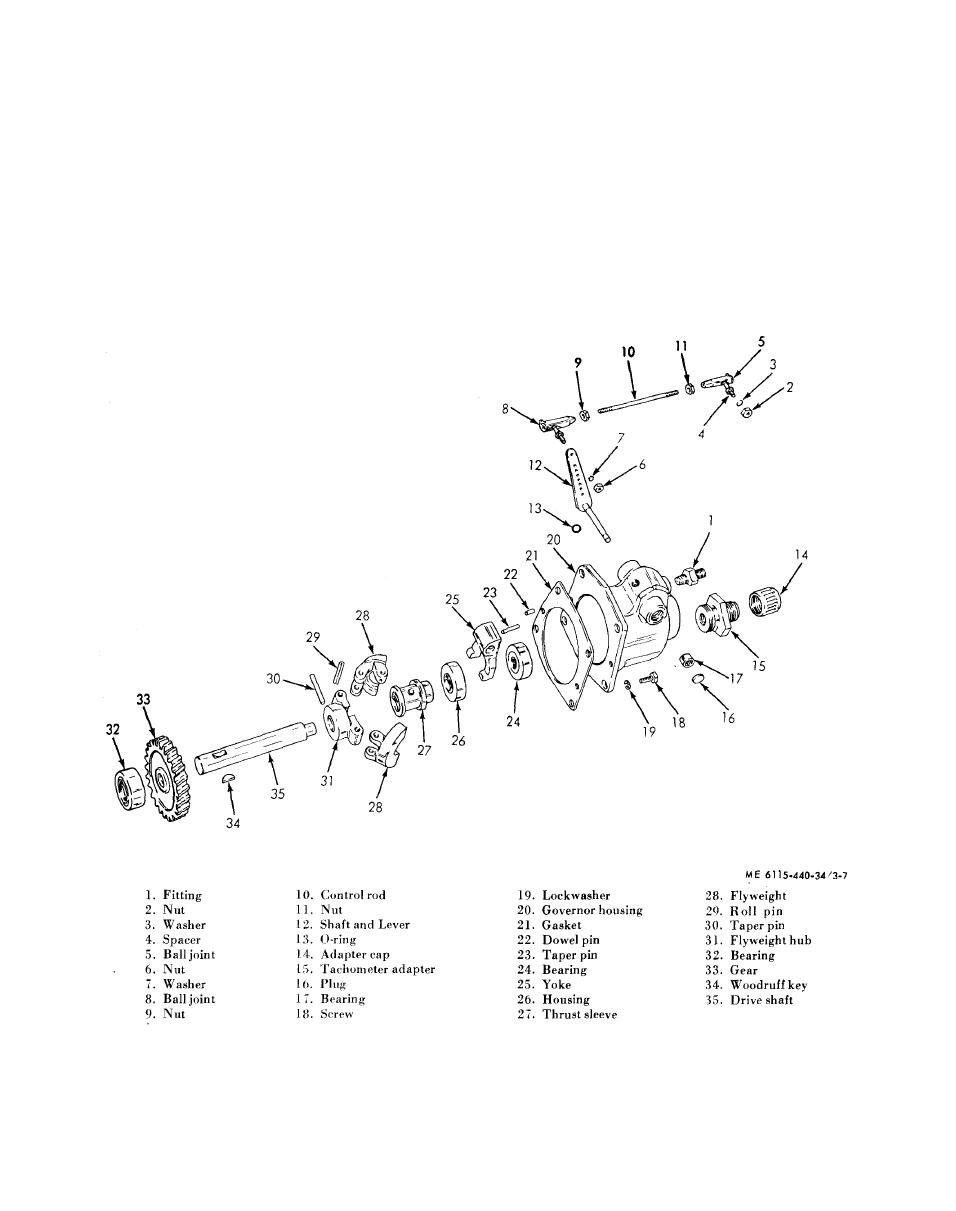
 3-11. Governor Assembly
b. Disassembly. Refer to figure 3-7 and
disassemble the governor assembly in numerical
a. Removal.
sequence.
(1) Remove the manifold (TM 5-6115-440-
20).
c. R e a s s e m b l y . Refer
to
figure
3-7
and
reassemble the governor assembly in the reverse
(2) Remove oil line from the restricted oil line
order of disassembly.
fitting (1, fig. 3-7).
d. Installation.
(3) Remove nut (2) and washer (3), and
(1) Install in the reverse order of removal.
remove the spacer (4) and control rod ball joint (5)
(2) Install the intake manifold (TM 5-6115-
from the carburetor.
440-20).
(4) Remove nut (6) and washer (7) and
e. Adjustment. Adjust the governor (TM 5-6115-
remove control rod ball joint (8) from the control
440-20).
shaft and lever (12).
Figure 3-7. Governor assembly, disassembly and reassembly.
3-8
|
|
Privacy Statement - Press Release - Copyright Information. - Contact Us |