 |
|||
|
|
|||
|
Page Title:
Figure 3-6. Governor control assembly disassembly and reassembly. |
|
||
| ||||||||||
|
|
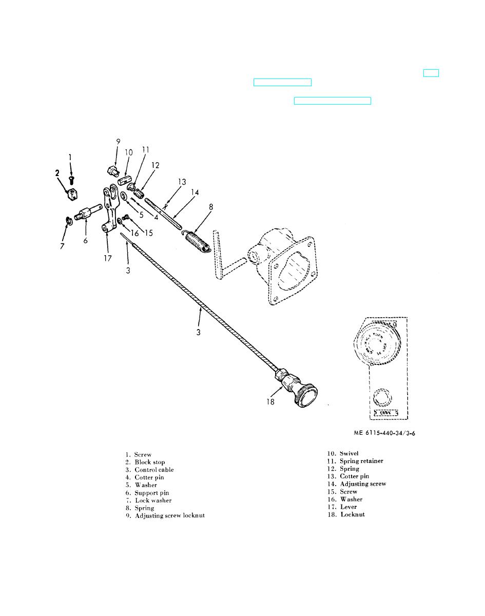 removing nut (18, fig. 3-6) and pulling cable
(2) Loosen stop block screw (1, fig. 3-6) and
thru control panel.
remove block stop (2) from control cable (3).
(3) Remove cotter pin (4) and washer (5) from
c. R e a s s e m b l y . R e f e r t o f i g u r e 3 - 6 a n d
speed lever support pin (6) and remove the support
reassemble the governor control assembly.
pin and washer (7).
d. Installation.
(4) Disconnect spring (8) from governor
(1) Install in the reverse procedure of removal.
control lever.
(2) Install the intake manifold assembly (TM
b. D i s a s s e m b l y . R e f e r t o f i g u r e 3 - 6 a n d
5-6115-440-20).
d i s a s s e m b l e the governor control assembly in
e. A d j u s t m e n t . A d j u s t the governor control
numerical sequence.
a s s e m b l y (TM 5-6115-440-20).
NOTE
The control flex cable may be removed by
Figure 3-6. Governor control assembly disassembly and reassembly.
3-7
|
|
Privacy Statement - Press Release - Copyright Information. - Contact Us |
