 |
|||
|
|
|||
|
|
|||
| ||||||||||
|
|
 T M 5-6115-423-15
reset automatically after resistive ele-
28 volts
DC at 10 amperes for opera-
ments cool down.
tion of the power absorber fan motors.
(7) Terminal strip. Four terminal studs
variable transformer (fig. 4) provides
(L 1, L2, L3, and Lo) with 3/8-24
changeable control of load from 0 to
threads and bakelite connecting knob,
3 KW. It is operated manually by a
are located on the terminal strip (fig.
variable control knob located on the
2) which is located at the back of
control panel. With the variable load
the load bank, Two copper shorting
switch and the variable control knob,
links tie terminals together for single
the variable transformer controls
phase operation.
loads from 0.5 KW to 3 KW on
single phase or balanced 3-phase op-
volt minimum, 200 volt maximum
eration. Therefore, using a combina-
pull-in, operates over a frequency
tion of the fixed load switches and
range of 50-1000 cps (cycles per
the variable load control, loads from
second). It senses the input power of
0.5 KW to 30 KW may be provided.
the source as determined by connec-
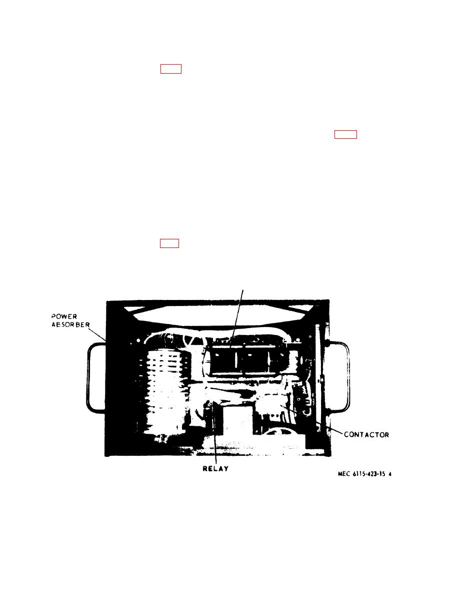
(5) Contactor. A 3 PST (Pole Single
tion to terminal strip TB1,
threw) 200 ampere, 200 volt AC;
(9) Auto transformers. The auto trans-
400 cycle 28 VDC coil contactor (fig.
formers are only in use when the
4) incorporated into the circuitry
load bank is used for high voltage
makes and breaks applied loads as set
(240/416 VAC). They reduce the
Up by increment or air-flow switches.
high voltage to low voltage so the
(6) Rectifier. The rectifier (fig. 3) con-
same components can be used regard-
verts the line voltage to a nominal
less of whether the load bavnk is used.
VARIABLE
TRANSFORMER
Figure 4. Load bank, top view, cover removed.
7
|
|
Privacy Statement - Press Release - Copyright Information. - Contact Us |
