 |
|||
|
|
|||
|
Page Title:
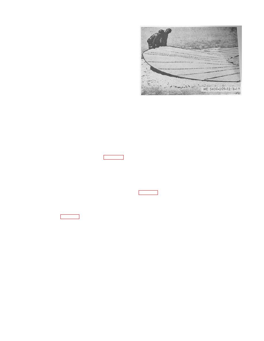
Figure 8-19. Lifting and supporting outer edge of installed bottom sections |
|
||
| ||||||||||
|
|
 TM 5-5430-209-12
(d) Install finger-tightened nuts on bolts in the
lap seam and follow the procedure in c (4) above.
(e) Lift free side of last section (1) and slide
several pieces of lumber (2) under it. The lumber
supports the last section and, at the same time, acts as
slide bars in adjusting the sections.
(f) Place several pieces of bolt channel (5)
equally spaced on top of sections (1 and 7) along the
length of the seam. Remove appropriate nuts from
bolts (3) in left lap seam of first intermediate section (4).
Attach one end of each bolt channel (5) to a bolt in the
seam and secure with a nut.
(g) Insert drift pins (5) through channels (5)
and last section (1), with the pins bearing against the left
Figure 8-19. Lifting and supporting outer edge of
edge of first bottom section (7). This will produce
installed bottom sections
enough leverage to bring the right lap seam of last
section (1) in alinement with the bolts in the left lap
seam of first bottom section (7).
(e) Move the support progressively toward or
(h) With last section (1) in final position, the
away from the space remaining for the installation of
right lap seam will drop over the bolts in the left lap
this section as required. As the supports are shifted, the
seam of first section (7) upon removal of lumber (2) and
slope made in the jointed sections will cause the weight
channels (5). Install finger-tightened nuts on the bolts.
of each section to react with the angle of the slope,
NOTE
forcing the raised sections to slide down the slope. The
If necessary, combine the following instructions
direction of shift combined with the weight of the
with the adjusting procedure (1)above
sections involved, will change relationship of the bolts in
(2) Alternate adjusting method.
the left lap seam of first section (7) with the right lap
(a) Adjust next-to-last section (8, fig. 8-18)
seam boltholes in last section (1).
so the left lap seam of last section (1) will slip over the
(f) With last section (1) in final position, the
bolts in the right lap seam of next-to-last section (8).
right lap seam will drop over the bolts in the left lap
(b) Install finger-tightened nuts on the bolts
seam of first section (7).
and follow the procedure in c (4) above.
(g) Install finger-tightened nuts on the bolts.
(c) Lift the free side of last section (1) and
(3) Installing special gasket.
slide several short lengths of 2-by 4-inch lumber under
(a) When the left lap seam of last section (1,
it. The lumber will keep the section clear of the bolts in
the left lap seam of first section (7) and act as slides
of next-to-last section (3), a small gap (2) is formed
during the shifting of the sections.
under the seam. This is caused by the off-spacing of
(d) Lift a portion of the outer edge of the
the joining seams of the sections.
installed sections and place it on boxes or other types of
easily moved supports (fig. 8-19).
8-10
|
|
Privacy Statement - Press Release - Copyright Information. - Contact Us |
