 |
|||
|
|
|||
|
Page Title:
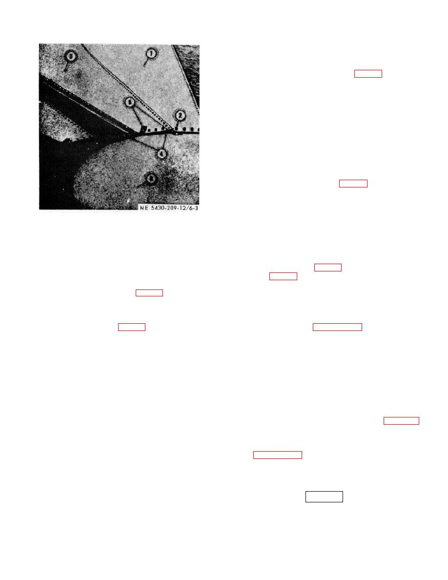
Figure 6-3. Installation of bottom plates |
|
||
| ||||||||||
|
|
 TM 5-5430-209-12
each channel as bottom plates are installed on the center
support base.
b. First Plate.
(1) Place small end of plate (1, fig. 6-3) over
center column base bolts (2).
(2) Place a steel recessed washer, cupped side
down, over each bolt and install a nut loosely on each bolt.
NOTE
Do not tighten nuts on bolts until all bottom plates
have been installed.
c. First Intermediate Plate.
NOTE
Wedge gaskets must be used wherever three
plates are joined together.
(1) Place wedge gasket (4, fig. 6-3) over strip
gasket (5) at right edge of first plate.
NOTE
Use 1/2 by 11/2 inch bolts wherever three plates
1.
FIRST BOTTOM PLATE
are joined together.
2.
BOLT
3.
FIRST INTERMEDIATE PLATE
(2) Face small end of plate. Install this plate to left
4.
WEDGE GASKET
of first plate, or in a counterclockwise direction, around the
5.
STRIP GASKET
tank foundation.
6.
CENTER SUPPORT BASE
(3) Place small end of plate over bolts (2) with right
lap seam laid over bolts (3, fig. 6-2) in the left lap seam of
Figure 6-3. Installation of bottom plates.
first plate (1, fig. 6-3).
(4) Install steel recessed washer and nut on each
(3) Place bolt channel (4, fig. 6-2) under the
bolt along the lap seam and on the center base bolts as
right and left lap seams of the plate. These channels
described in b (2) above.
d. Remaining Intermediate Plates. Install remaining
line up with and about the inner ends, of the 24-hole
channels (2). Insert bolts (3) through all bolt holes.
intermediate plates as described in c above.
(4) Install gasket (5, fig. 6-3) along the full
length of the right and left lap seams. Allow a 1 1/2 -
last plate.
bolthole overlap at each end.
6-4. Tightening Tank Bottom
NOTE
When there is a break in the gasket material,
Start at small end of bottom plates and work toward large
the ends should overlap 2 boltholes and be cut
end, tightening nuts evenly in each lap seam. Avoid
squarely across the second hole. Sealing
crushing the gaskets. Tighten nuts to a maximum of 40 to
compound must be applied to each end of the
50 foot-pounds of torque.
overlap strip to insure a leakproof joint.
6-5. Bolt Replacement Plug
(5) Upon completion of the assembly, move this
If threads are stripped on one or more bolts, drive out bolt
plate to its approximate installation position on the tank
and use a bolt replacement plug as instructed in paragraph
foundation.
3-4.
d. Assembling Intermediate Bottom Plates. There
6-6. Testing Seams for Leakage
are eighteen intermediate plates assembled with
channels and strip gaskets. Except that channels are
Refer to paragraph 3-5 and test tank bottom seams for
placed under right lap seams only, follow assembly
leakage utilizing the vacuum seam tester provided with the
procedures outlined in c above. These procedures do
storage tank erection outfit.
not apply to the last bottom plate, since no further
assemblies are made on it. Keep the last bottom plate
6-7. Sealing Seams
separated from all others until it is installed.
WARNING
If tank is to be used for water storage, do not
6-3. Installation of Bottom Plates
apply sealing compound to tank bottom.
a. General. With the first bottom plate in its
Sweep bottom of tank clean after testing seams. With
approximate position, lay the remaining plates around
bottom dry, apply sealing compound to all bolts and seams.
the tank foundation. Place bolt retaining boards under
6-3
|
|
Privacy Statement - Press Release - Copyright Information. - Contact Us |
