 |
|||
|
|
|||
|
Page Title:
Section IV. ASSEMBLY AND INSTALLATION OF TANK DECK |
|
||
| ||||||||||
|
|
 TM 5-5430-209-12
Section IV. ASSEMBLY AND INSTALLATION OF TANK DECK
4-14. General
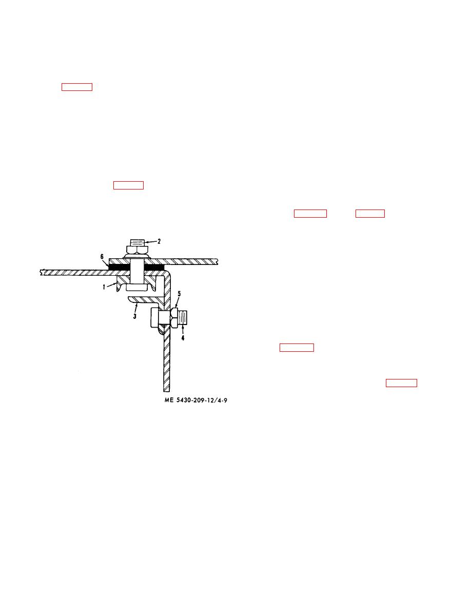
d. Place angle (3) against inside of flange. Insert
four bolts (4), equally spaced, through the angle and
The assembled deck consists of 10 tapered, flat, steel
flange. Install and tighten nuts (5) on bolts (4).
plates (2, fig. 4-8). There are three special plates: two
e. Turn plate over with flange down. Install gasket
are fitted with a pressure vacuum valve, and the third
with a liquid level indicator.
All plates are
(6) along full length of right lap seam. Allow 2-bolthole
interchangeable.
overlap at each end.
4-15. Layout and Assembly of Deck Plates
4-16. Assembly of Special Plates
WARNING
a. Lay plates around the outer perimeter of tank
If this tank is to be used for water
foundation.
b. Place blocking on ground spaced to fit inside the
storage, omit the two pressure
vacuum valves. Install blind hatch
confines of the plate. Lay plate on blocking with flange
flange sets in place of pressure
up.
vacuum valves.
the flange. Insert bolt (2) through all except the end
a. Pressure Vacuum Valve. Install a pressure
boltholes of plate and channel. Make sure bolt heads
vacuum valve on the pressure vacuum valve opening
set square in the channel.
deck plate (2, fig. 3-20) and (2, fig. 4-8) as follows:
(1) Insert 1/2 by 1-1/2-inch bolts through eight
two-bolthole channels. Work through the 8-inch hole
and insert bolts through plate. Place blocking under bolt
heads to hold them in place while installing the gasket.
(2) Install a 16-hole gasket over the bolts.
(3) Install valve over bolts.
(4) Install nuts on bolts and tighten bolts.
(5) Remove blocking used in step (1) above.
b. Level Indicator. The level indicator deck plate is
installed with the level indicator fittings as received.
4-17. Installation of Deck Plates
a. Layout of Assembled Plates. As plates are
assembled, raise them up and stand them against the
scaffold (fig. 3-20). Place each plate so that it straddles
a vertical seam of the side staves in its approximate
installation position, counterclockwise.
b. Adjustment of Center Support Ladder.
(1) Check and adjust ladder (fig. 4-7) to the
correct height before installing deck plates.
The
distance from top of tank bottom to outer face of top
flange of the dome (7) is 9 feet, 3 13/32 inches. Raise
or lower the ladder as required.
1.
DECK PLATE CHANNEL
(2) Place a jack under one of the ladder steps
2.
BOLT
3.
RAFTER BOLT RETAINING ANGLE
(4). Adjust ladder so that in its final position one set of
4.
BOLT
holes in bottom of the rails (1 and 2) lines up with holes
5.
NUT
in the brace (8). Lock the jack.
6.
STRIP GASKET
(3) Insert bolts (3) through the proper bolt
holes in brace (8) to match the top holes in rails (1 and
Figure 4-9. Deck plate assembly.
2). Install nuts (5) on bolts (3); tighten the bolts.
4-9
|
|
Privacy Statement - Press Release - Copyright Information. - Contact Us |
