 |
|||
|
|
|||
|
Page Title:
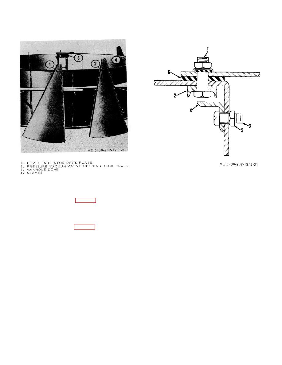
Figure 3-20. Deck plates ready for installation |
|
||
| ||||||||||
|
|
 TM 5-5430-209-12
1. BOLT
2. DECK PLATE CHANNEL
Figure 3-20. Deck plates ready for installation.
3. BOLT
4. RAFTER BOLT RETAINER ANGLE
3-14. Layout and Assembly of Deck Plates
5. NUT
a. Lay out the plates (1, fig. 3-20) around the outer
6. STRIP GASKET
perimeter of tank foundation.
7.
b. Place blocking on ground spaced to fit inside the
Figure 3-21. Deck plate components
confines of the plate. Lay the plate, flange up, on
blocking.
d. Place an angle (4) against the inside of the
C. Place a channel (2, fig. 3-21) on the right lap
flange. Insert four equally spaced "2 -by 1-inch bolts (3)
seam at the flange. Insert L2-by 114-inch bolts (1)
through the angle and flange. Install nuts (5) on bolts
through all except end boltholes of plate and channel.
(3). Tighten bolts.
Make sure bolt heads set square in channel.
e. Turn plate over with flange down. Install gasket
(6) along the full length of right lap seam. Allow a
2bolthole overlap at each end.
3-18
|
|
Privacy Statement - Press Release - Copyright Information. - Contact Us |
