 |
|||
|
|
|||
|
|
|||
| ||||||||||
|
|
 TM 5-5430-209-12
3-15. Assembly of Special Plates
(2)
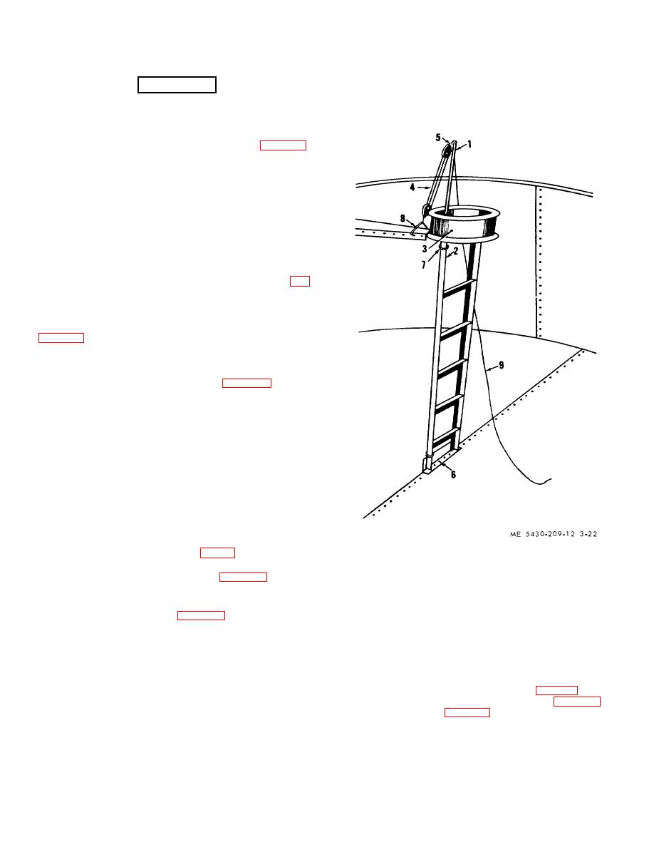
Drop open bottom of gin pole (1) over a bolt (6). With
the pole standing as near vertical as possible, apply lashing
WARNING
(7) to pole and rail. Locate lashing near the bottom and top of
If tank is to be used for water storage, omit the pressure
rail.
vacuum valve. Install blind hatch flange set in place of
pressure vacuum valve.
a. Pressure Vacuum Valve.
(1)
Install a pressure vacuum valve (5, fig. 3-23)
through two-bolthole channels. Work through the 8inch hole
and insert bolts through the plate. Place blocking under bolt
heads to hold them in place while installing gasket.
(2)
Install a 16-hole gasket over the bolts.
(3)
valve over bolts.
(4)
Apply nuts to bolts and tighten.
(5)
Remove blocking used in step (1) above.
b. Blind Hatch Flange Set. Install blind hatch flange set
on the water inlet opening deck plate. Use the same bolts.
channels, and gasket as in steps a (1) and (2) above. Follow
above procedures.
c. Level Indicator. The level indicator deck plate (1, fig.
3-20) is installed, with level indicator fittings as received.
3-16. Installing Deck Plates
a. Layout of Assembled Plates. As plates are
assembled, raise them up and stand them against the scaffold
plate so that it straddles a vertical seam of the side staves in
its approximate installation position.
b. Adjustment of Center Support Ladder.
(1)
Check and adjust ladder (fig. 3-19) to the
correct height before installing deck plates. Distance from top
of the tank bottom to outer face of top flange of the dome (7)
is 9 feet, 1/8 inch. Raise or lower ladder as required.
(2)
Place a jack under one of the ladder steps (4).
Adjust ladder so that in its final position, one set of holes in
the bottom of rails (1 and 2) lines up with holes in brace (8).
Lock the jack.
(3)
Insert bolts (3) through the rails (1 and 2) and
brace (8). Apply nuts (5) to bolts (3); tighten the bolts.
(4)
Unlock and remove jack.
NOTE
When all deck plates have been installed on tank check height to
outer face of top flange of manhole dome above the top of the
tank bottom. If it is not the required height. adjust ladder until It Is
the correct height. Insert bolts (3. fig. 3-19) in alined bolt holes
1.
GIN POLE
and tighten nuts (5).
2.
LADDER RAIL
c. Gin Pole. To install deck plates (fig. 3-20), remove
3.
MANHOLE DOME
4.
BLOCK AND TACKLE
and assemble gin pole components, less the foot spike, that
5.
HEAD BLOCK EYE
are provided in the storage tank erection outfits.
6.
LAP SEAM BOLT
(1)
Raise the pole (1, fig. 3-22) alongside one of
7.
LASHING
the ladder rails (2). As the top of the pole (1) passes through
8.
ROPE DECK HOOK
the dome (3), attach block and tackle (4) to head block eye
9.
HAUL LINE
(5).
Figure 3-22. Gin pole installed
d. Installing First Deck Plate. The first plate installed is
the plate with the pressure vacuum valve (2. fig. 3-20).
(1)
Attach two rope deck hooks (8. fig. 3-22) to
small end of plate (4, fig. 3-23) while it stands against the
scaffold.
3-19
|
|
Privacy Statement - Press Release - Copyright Information. - Contact Us |
