 |
|||
|
|
|||
|
Page Title:
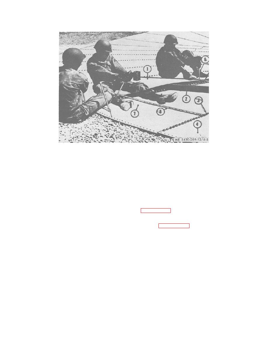
Figure 4-5. Adjusting installed bottom plates |
|
||
| ||||||||||
|
|
 TM 5-5430-209-12
1.
LAST BOTTOM PLATE
2.
BOARDS
3.
BOLTS
4.
FIRST INTERMEDIATE BOTTOM PLATE
5.
BOLT CHANNEL
6.
DRIFT PIN
7.
FIRST BOTTOM PLATE
Figure 4-5. Adjusting installed bottom plates.
4-5. Bolt Replacement Plug
(f) Place several pieces of bolt channel
(5) along the length of last plate (1) with their outer ends
If threads are stripped on one or more bolts, drive out
touching the right edge of first intermediate plate (4).
bolt and use a bolt replacement plug as instructed in
(g) Insert drift pins (6) through channels
(5) and last plate (1), with pins bearing against the left
4-6. Testing Seams for Leakage
edge of first plate (7). This will produce sufficient
leverage to bring the right lap seam of last plate (1) in
Refer to paragraph 3-5 and test tank bottom for leaks
alinement with bolts in left lap seam of first plate (7).
utilizing the vacuum seam tester incorporated in the
(h) With last plate (1) in final position,
storage tank erection outfit.
NOTE
the right lap seam will drop over bolts in left lap seam of
first plate (7) upon removal of boards (2) and channels
Do not move off a tested area with
(5). Install steel washers and nuts, as described in a (2)
leaks until all points of leakage have
above.
been stopped.
NOTE
4-7. Sealing Seams
All bolts, except chime bolts, must have
WARNING
a steel washer under the nut.
If tank is to be used for water
4-4. Tightening Tank Bottom
storage, do not apply sealing
Start at small end of plates and work toward large end,
compound to tank bottom.
tightening nuts uniformly and carefully; avoid crushing
Sweep tank bottom clean after testing the seams. With
gaskets. A maximum of 40 to 50 foot-pounds of torque
bottom dry, apply sealing compound to all bolts and
should be used.
seams.
4-5
|
|
Privacy Statement - Press Release - Copyright Information. - Contact Us |