 |
|||
|
|
|||
|
|
|||
| ||||||||||
|
|
 TM 38-400/NAVSUP PUB 572/AFMAN 23-210 MCO 4450.14/DLAM 4145.12
lag screw head projects beyond the outside face of the
snubbing block and with a wrench turn the lag screw into
the side of the skid until 1/2 inch penetration is obtained.
The bite of the screw tip into the side of the skid will
serve as a retarder to control lengthwise and upward
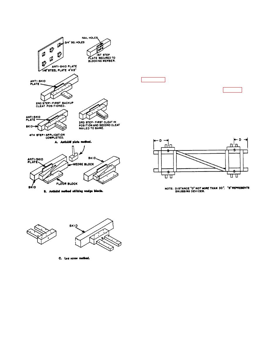
movement. The antiskid method is basically the same
except that a plate is inserted in lieu of a lag screw. The
method of arrangement for placing either the antiskid
plate or the lag screw snubbing device is shown by
snubbing devices from ends of the skid should be
approximately 24 inches to 30 inches (fig 3-17). The
snubbing devices on each side of the skid should be
equal in number and located directly opposite. The
number of snubbing devices to be employed on each
side of skid will vary with the weights of the desired
amount of restriction of movement. Generally, the
number varies from two to five devices on each side of
the skid. After end devices are located, the additional
devices are spaced in between.
Figure 3-17. Location of snubbing devices.
(3) Application and use.
The snubbing
devices should be used on machinery (especially
legged-type), boats, and those commodities that should
be protected from sudden or severe shock.
(4) Several items cleated together. The use
of the snubbed load is recommended wherever
practicable.
c. Floating load. The floating load absorbs a great
amount of shock pressure as containers slide over the
floor of the car, thus ridding with the "punch." The
materials may or may not be palletized. However, the
pallet loads or containers are secured in a unit by
Figure 3-16. Snubbing machine.
binding with steel straps. Units may be placed in each
end of the car or as a single unit extending through the
(2) Application of snubbing devices.
In
doorway area. Space for floating may be at each end
applying the lag screw snubber, the lag screw is turned
wall and doorway, all in the doorway, or with a single
in, in a predrilled hole in the snubbing block, until the
unit at the end walls. There are variations of this load
screw tip is flush with the inside faces. of the block.
which are termed "Restricted" floating loads. (For
The snubbing block and the backup cleat are securely
additional details, see AAR pamphlets 14 and 21
nailed and spiked to the floor. Measure the amount the
3-49
|
|
Privacy Statement - Press Release - Copyright Information. - Contact Us |