 |
|||
|
|
|||
|
Page Title:
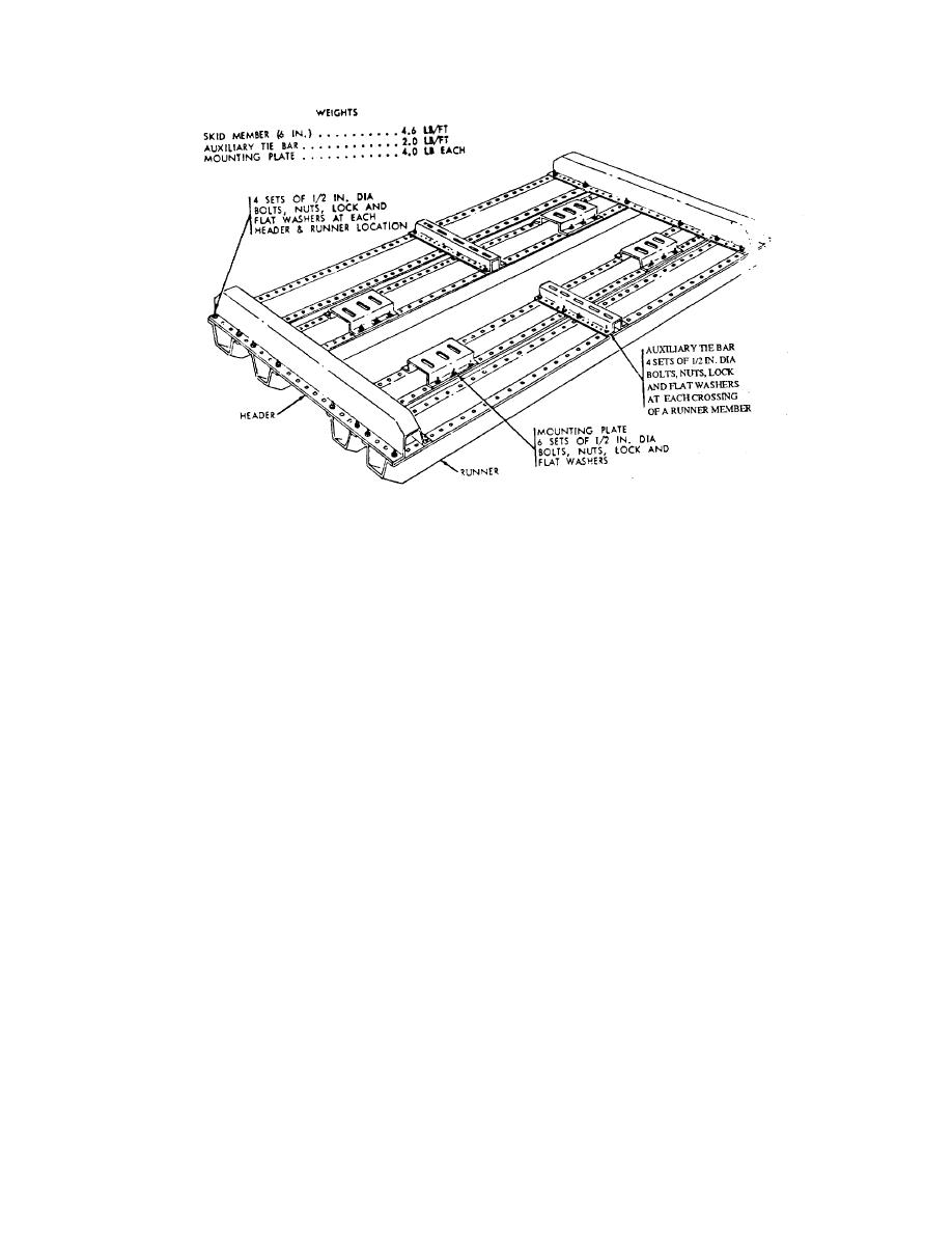
Figure 8-9. Type I Aluminum Skid Assembly. |
|
||
| ||||||||||
|
|
 TM 38-260
Figure 8-9. Type I Aluminum Skid Assembly.
(b) The skid would have the same safe carrying capacity without the two outrigger
runners.
(c) Outrigger runner beams need not be used when protruding components have been
removed or when the clearance requirements can otherwise be met without outrigger runners.
(d) For equipment weighing over 24,000 pounds (10,886kg) additional runner beams
and hold down points are required.
(e) Additional runners may also be required to increase the rigidity of the skid for
specific items of IPE, or to provide the necessary hold down points for machines with irregular-
shaped bases.
(4) Header beams. Each header beam shall be attached to the runner beams at right
angles with four carriage bolts at each point of intersection.
(5) Mounting plates. Each mounting plate is designed to carry a maximum of 6,000
pounds (2,722kg). One mounting plate is required for each hold down bolt, clamp, or device
used to secure the equipment to the skid. The minimum number of mounting plates for machines
of various weight is indicated in MIL-HDBK-701. Mounting plates are also used as supports
under heavy columns.
(a) Mounting plates shall be placed parallel with runner beams except where hold down
8-29
|
|
Privacy Statement - Press Release - Copyright Information. - Contact Us |
