 |
|||
|
|
|||
|
Page Title:
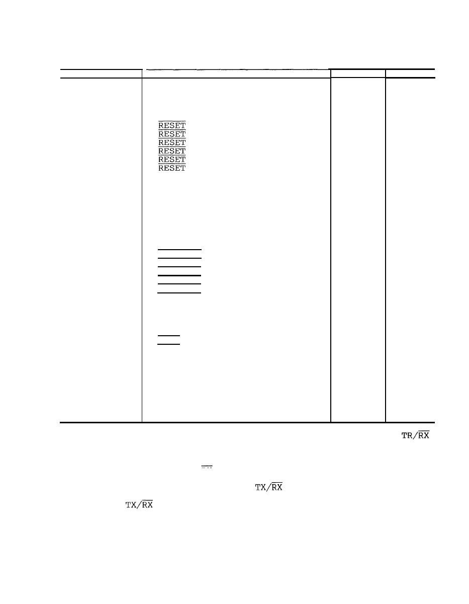
Table 3-2. Decoder CCA A4 Test Point Signals |
|
||
| ||||||||||
|
|
 TM 325865-216-24&P
Decoder CCA A4 Test Point Signals
From
To
Signal
Test Point
TP1
U4B-6
U5A-1
U3A-6
U2-9
TP2
U3A-6
U1-9
TP2
U2-8
U3B-8
TP3
U18
U3B-8
TP3
U14A-13
U5A-13
TP4
U14A-13
U5B-10
TP4
U14A-13
U6-10
TP4
U14A-13
U81
TP4
U14A-13
U9-1
TP4
U14A-13
U10-1
TP4
NRZ DATA
U6A-3
U4B-4
TP5
NRZ DATA
U6A-3
TP5
U4D-12
NRZ DATA
U6A-3
U3C-1
TP5
NRZ DATA
U6A-3
TP5
U4A-1
TP5
NRZ DATA
U6A-3
U2-1
MANCON 1
U5A-3
U4D-13
TP6
TP6
MANCON 1
U5A-3
U3C-13
TP6
MANCON 1
U5A-3
U4A-2
TP6
MANCON 1
U5A-3
U3B-11
TP7
MANCON 2
U5B6
U1lA-1
TP7
MANCON 2
U5B-6
U4B-5
U5B6
MANCON 2
U3A-4
TP7
MANCON 1
TP8
U5A-2
U5B-11
TP8
U5A-2
MANCON 1
U12A-5
TP9
U11C-8
U5A-4
PARITY
U65
TP10
U12A-4
PARITY
U6-5
U7-4
TP10
U4A-3
U6-11
TP11
U13F12
U6-8
TP12
DATA
U13C-6
U6A-4
TP13
U13C-6
DATA
TP13
U11B-5
MANCON 2
U5B-5
U12A-2
TP14
MANCON 2
U5B-5
U3C-2
TP14
MANCON 2
U5B-5
TP14
U3B-9
U12A-6
LATCH DATA
U20A-1
TP15
LATCH DATA
U8-9
TP15
U20A-1
U9-9
LATCH DATA
TP15
U20A-1
U10-9
LATCH DATA
TP15
U20A-1
the B0 through B4 subband output to the control loqic CCA. The
signal specifies the transmit-or receive operating-mode and passe's to
control logic CCA A3, relay driver U17, and line driver U19B.
For the transmit mode, TX/RX is high, and the driver U17 outputs
operate RF relays K1 and K2 to connect the RF path through RF switch
assembly S2. For the receive mode,
is low, the relays are
normal, and the RF switch assembly is bypassed.
Relay driver U19B
signal to external system equipment as the XMT RDY
applies the
signal.
|
|
Privacy Statement - Press Release - Copyright Information. - Contact Us |