 |
|||
|
|
|||
|
|
|||
| ||||||||||
|
|
 TM 32-5865-216-24&P
Motor control CCA A2
Feedback switch CCA S4
RF monitor CCA A6
Power supply CCA A1
Extender CCA A5
CONTROL CIRCUIT.
The tunable coupler receives 16-bit, Manchestercoded command
words as serial data input at connector pins J4C and J4D.
The
control circuit decodes each command word to select the transmit or
receive operating mode and tune RF switch assembly S2 to a specified
100-kHz bandwidth. Table 3-1 lists the function of each bit in the
command word.
circuit converts the command word input into
subband, and data
strobe outputs to control logic CCA A3 and RF relays K1 and K2.
points.
As shown in figure FO-2, the digital input passes through
line receiver U18A and parity flipflop U6A to command word detector
and decoder U1 through U5 and U8 through U12.
Three consecutive high
bits indicate a command word follows and provide synchronization data
to clock generator U14. The l-MHz CLK, and RESET outputs of multi-
vibrators U14A and U14B clock the command word into parity flipflop
and shift registers U1 and U2.
If parity is correct (even), the Q
output of U6 clocks the command word into flipflops U8 through U10.
The Q output of U6 also passes to the status circuit (U7) and control
logic CCA A3 as the parity and data strobe signals, respectively.
Flipflops U8 through U10 convert the 16bit command word into 12 fre
quency bits and (DBO through B11) and
signal.
Switch
position
decoder U15 and U16 converts the DB0 through DB11 signals into
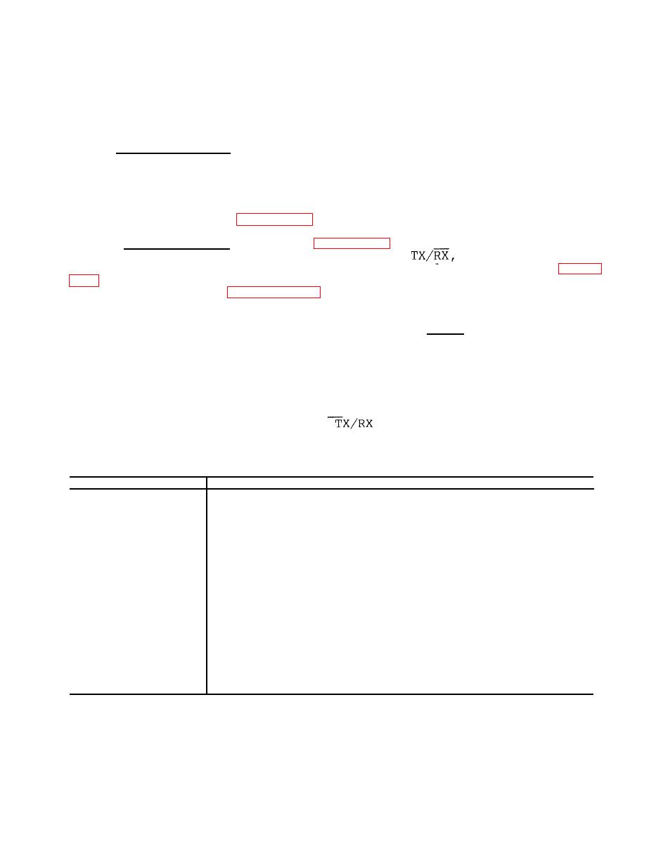
Command Word Bit Functions
Bit
Function
o
Frequency 100 kHz BCD 1
Frequency 100 kHz BCD 2
1
2
Frequency 100 kHz BCD 4
Frequency 100 kHz BCD 8
3
4
Not used
Parity (even for 16 bits)
5
Not used
6
7
Transmit/Receive (1=TX, 0=RX)
Frequency 1 MHz BCD 1
8
Frequency 1 MHz BCD 2
9
10
Frequency 1 MHz BCD 4
11
Frequency 1 MHz BCD 8
12
Frequency 10 MHz BCD 1
13
Frequency 10 MHz BCD 2
14
Frequency 10 MHz BCD 4
15
Frequency 10 MHz BCD 8
|
|
Privacy Statement - Press Release - Copyright Information. - Contact Us |
