 |
|||
|
|
|||
|
|
|||
| ||||||||||
|
|
 or lamp assembly (fig. 3-9), check for rust or corrosion.
3-10.
Replacement of Reticle Lamps and Ground
(2) Inspect ground strap; check for rust or
Strap (Figs. 3-6 and 3-9)
corrosion. Check soldered connections of terminals.
(3) Inspect contact assembly; check for rust
a. Disassembly.
or corrosion.
(1) Twist to remove lampholder assembly (3.
(4) Inspect the mirror, if mirror is glass check
if broken, cracked, or chipped. If mirror is metal, clean
lamp (1).
reflecting surface.
(2) Unlock and open cover (fig. 3-9). Push in
(5) Inspect plate and hardware; check for rust,
and twist lamp (1) to remove from lamp assembly.
worn, burred, or broken threads.
(3) Detach hardware, items(2, 4 and 5, fig. 3-
c. Repair. Repair is limited to replacement of all
(4) Remove screw (7, fig. 3-6), and washer
items inspected in b above.
(8). Pull contact assembly (9) out as far as possible from
the support.
d. Assembly..
(5) Unsolder wire from contact and remove
(1) Apply sealing compound, MIL-S-11031, to
the assembly.
the inner flange of plate (12, fig. 3-6 or 3, fig. 3-9).
(6) Remove setscrew (10, fig. 3-6) and pull
support (14) from housing.
the plate opening with polished surface facing up. Wipe
off excess sealing compound.
securing plate with mirror attached to support. Lift plate
(3) Position plate, with mirror installed, on the
to remove.
respective support. Apply sealing compound, MIL-S-
from plate (12, fig. 3-6 or 3, fig. 3-9).
and secure the plate.
b. Inspection.
(1) Inspect lampholder assembly (3, fig. 3-6)
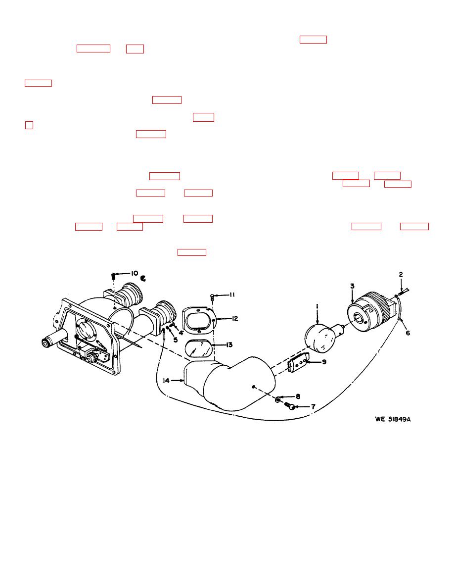
1- Lamp, sgl cont, 28V, 8624583
6 - Strap, ground, 10549759
11 - Screw, 2-56 1/4, (S),
2- Screw, 4-40 x 5/8, MS51957-18
7 - Screw, 4-40 x 1/4, MS51957-13
MS51959-3
3- Lampholder assembly, 10549783
8 - Washer, lock, No. 4, MS35333-70
12 - Plate, 8624587
4- Screw, 6 32 x 3/8, MS51957-28
9 - Contact assembly, 10549780
13 - Mirror, 11727579
5- Washer, lock No. 6, MS35333-71
10 - Setscrew, 6-32 x 3/16, (2),
14 - Support, 8624527
MS51029-17
Figure 3-6. Conventional reticle lampholder assembly-partial exploded view.
3-8
|
|
Privacy Statement - Press Release - Copyright Information. - Contact Us |
