 |
|||
|
|
|||
|
|
|||
| ||||||||||
|
|
 two plotted points, the operator must remember
that all parallel lines have the same azimuth.
Therefore, when a particular azimuth is rotated
over the index mark, every vertical line on the
grid pattern (fig. 13) is pointing along that same
azimuth. This means also that the azimuth of
any of the vertical lines of the grid pattern is
read at the index mark. To find the azimuth of
the target with respect to the firing position, ro-
tate the azimuth disk (fig. 12) until the two
pencil dots lie along one of the vertical lines on
the base grid, or, until they are the same distance
from the same vertical line with the target dot
toward the top of the plotting board. The WT
azimuth in this example may be read on the
azimuth scale at the index mark on the base.
(4) Determine the range between the firing
position and the target in meters by counting
the number of small grid pattern graduations
separating them when in the above position and
multiplying this number by 50 or 100, depending
on which scale on the grid pattern is used. The
WT range can also be determined by measuring
the distance, using one of the range scales on the
base.
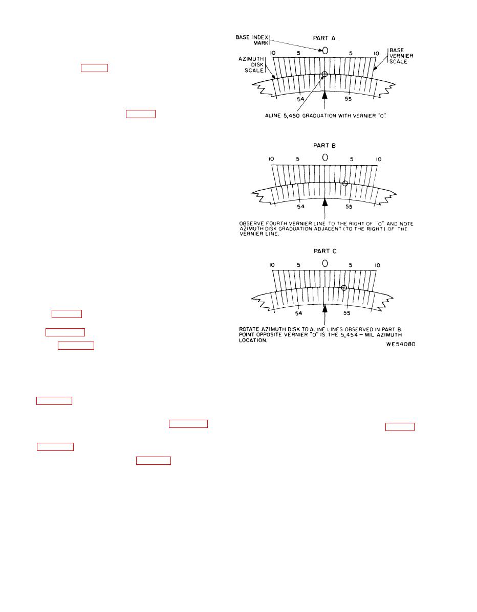
e. In many cases, the index mark does not
fall exactly on one of the 10-mil graduation lines
of the azimuth scale. When this occurs, the opera-
tor computing the range must use the vernier
scale to read the azimuth to an accuracy of one
mil (fig. 21). As an example, the use of the
vernier scale for setting azimuth 5454 is shown in
the figure 21.
Note. Figure 2-1 shows vernier setting method and does
not reflect the appearance of the vernier on plotting board
M17.
Figure 21. Use of vernier scale.
2-8. Uses for Plotting Board M17
Azimuth 5454 mils
OP to target:
a. To determine initial direction and range
Distance 1500 meters
(2) Procedure. To determine the azimuth
b. To determine WT mil values from the azi-
and range from the weapon to the target using
muth scale on the azimuth disk (para 2-9b).
the range scale along the index line (fig. 13),
where the smallest grid graduation represents
c. To solve problems involving mil relations
50 meters, proceed as indicated in (a) through
(d) below.
(a) Rotate the disk until 4150 mils is read
over the index mark on the base. Mark the disk
2-9. Sample Problems
with a pencil dot over the index line at the 550-
a. Determination of the Initial Azimuth and
meter graduation. This dot represents the loca-
R a n g e From the Weapon Firing Position to the
tion of the weapon (W).
Target.
(b) Rotate the disk until 5454 mils is
(1) Given. Observation post at the center
read over the index mark on the base. Mark the
(pivot point) of the disk.
disk with a pencil dot over the index line at the
Azimuth 4150 mils
1500-meter graduation. This dot represents the
OP to weapon:
location of the target (T).
Distance 550 meters
2-4
|
|
Privacy Statement - Press Release - Copyright Information. - Contact Us |
