 |
|||
|
|
|||
|
Page Title:
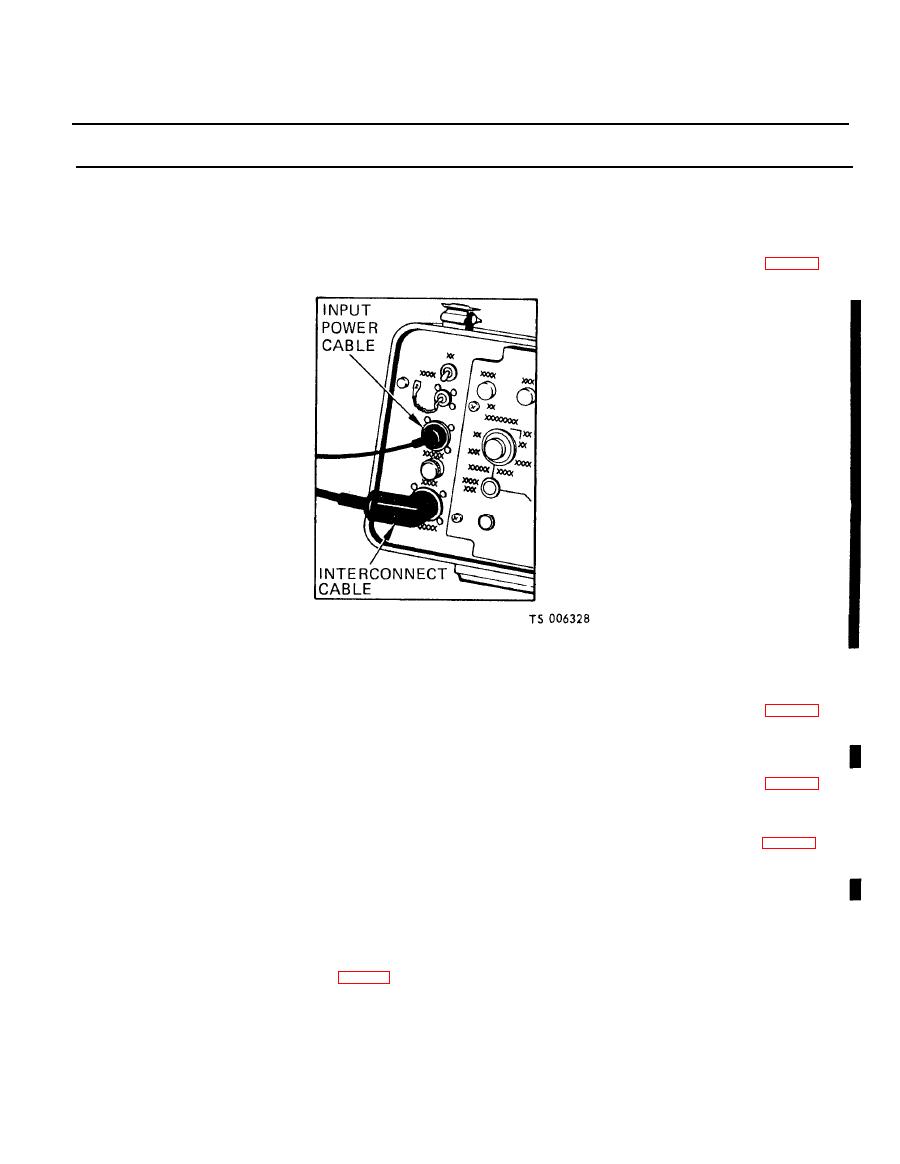
Figure 2-89. Disconnecting power cables. |
|
||
| ||||||||||
|
|
 TM 5-6675-250-34
Table 2-1. Troubleshooting - Continued
MALFUNCTION
TEST OR INSPECTION
CORRECTIVE ACTION
(1). Install a good printed circuit board, but do not tighten mounting screws. Connect the two
electrical connectors and secure by tightening two screws. Fasten ten screws that secure printed
circuit board to mounting brackets.
(2). Install electronic control panel assembly in case and secure with eight captive screws.
Step 8. Check for a defective ECU.
Replace existing ECU with an ECU that is operable, by disconnecting and connecting power cables (fig. 2-89).
If the system operates correctly with the new ECU, report the bad ECU to the next higher level of main-
tenance.
Step 9. Check for defective caging mechanism.
Replace existing GRU with a GRU that is operable, by disconnecting and connecting power cables (fig. 2-89).
If the system operates correctly with the new GRU, report the bad GRU to the next higher level of main-
tenance.
1 5 . INACCURATE AZIMUTH READING INDICATIONS.
Step 1. Check for a defective GRU.
Replace existing GRU with a GRU that is operable, by disconnecting and connecting power cables (fig. 2-89).
If the system operates correctly with the new GRU, report the bad GRU to the next higher level of main-
tenance.
Step 2. Check for a defective ECU.
Replace existing ECU with a ECU that is operable, by disconnecting and connecting power cables (fig. 2-89).
If the system operates correctly with the new ECU report the bad ECU to the next higher level of main-
tenance.
1 6 . THEODOLITE CONTROLS INOPERATIVE.
Step 1. Check for a defective theodolite.
a. Replace existing theodolite with a theodolite that is operable.
CAUTION
Ensure that the GRU is securely held when removing theodolite. Retain the GRU housing in the tripod assembly or a
holding fixture when removing the theodolite.
Change 1,
|
|
Privacy Statement - Press Release - Copyright Information. - Contact Us |
