 |
|||
|
|
|||
|
Page Title:
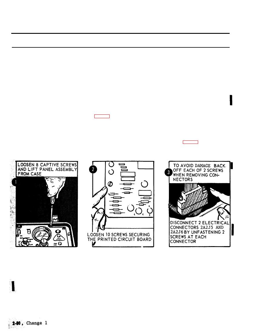
Figure 2-88. Removal of printed circuit board. |
|
||
| ||||||||||
|
|
 TM 5-6675-250-34
Table 2-1. Troubleshooting - Continued
MALFUNCTION
TEST OR INSPECTION
CORRECTIVE ACTION
(10). Press the anti-backlash setting tools into tbe index hole of the lower gear half and relax the
thumb and index finger.
(11). Connect the gearbox assembly electrical cable connector to the female receptacle on the housing
connector. Rotate the cable connector mounting screws in the clockwise direction, being careful
to alternate between tbe two screws after (2 to 3) turns.
(12). Place the cable betweeen the gearbox assembly mounting pads, so that it will be under the
gearbox when tbe gearbox is in final position.
(13). Rotate the follow-up shaft to the extreme clockwise position by turning theodolite mounting
plate.
(14). Install the gearbox assembly through the access and place it so that the mounting screw holes
are lined up.
(15). Apply sealent primer, MIL-S-22473, Grade N, Form R, to the threads, and allow to air dry.
Apply a small amount of thread locking sealant, MIL-S-22473, Grade N, Type II, to the
first few threads.
against the index pins (fig. 2-86) on the inner mounting pads and tighten the mounting screws
while maintaining the gearbox position.
(17). Remove tbe anti-backlash setting tool from the indexing hole.
(18). Install the gearbox assembly access and main connector housing cover. Secure each cover with
three mounting screws.
Step 7. Inspect printed circuit board for evidence of damage or failed components.
a. Loosen the eight captive ecrews and lift the electronic control panel assembly from the case (fig. 2-88).
CAUTION
TS 006337
b. Unfasten ten screws securing the printed circuit board to the mounting brackets and loosen the board to obtain access to
electrical connectors.
CAUTION
To avoid damage to the electrical connectors, alternately back-off each of the two attaching screws when removing the
connectors.
c. Disconnect two electrical connectors (2A2J5 and 2A2J6) by unfastening two screws at each connector. Remove printed
circuit board.
d. Inspect printed circuit board for visual evidence of cracked circuits, corrosion, burns, or other evidence of defects.
Replace a bad printed circuit board.
CAUTION
To avoid damaging the electrical connectors, alternate tightening each of the two screws during reassembly.
|
|
Privacy Statement - Press Release - Copyright Information. - Contact Us |
