 |
|||
|
|
|||
|
Page Title:
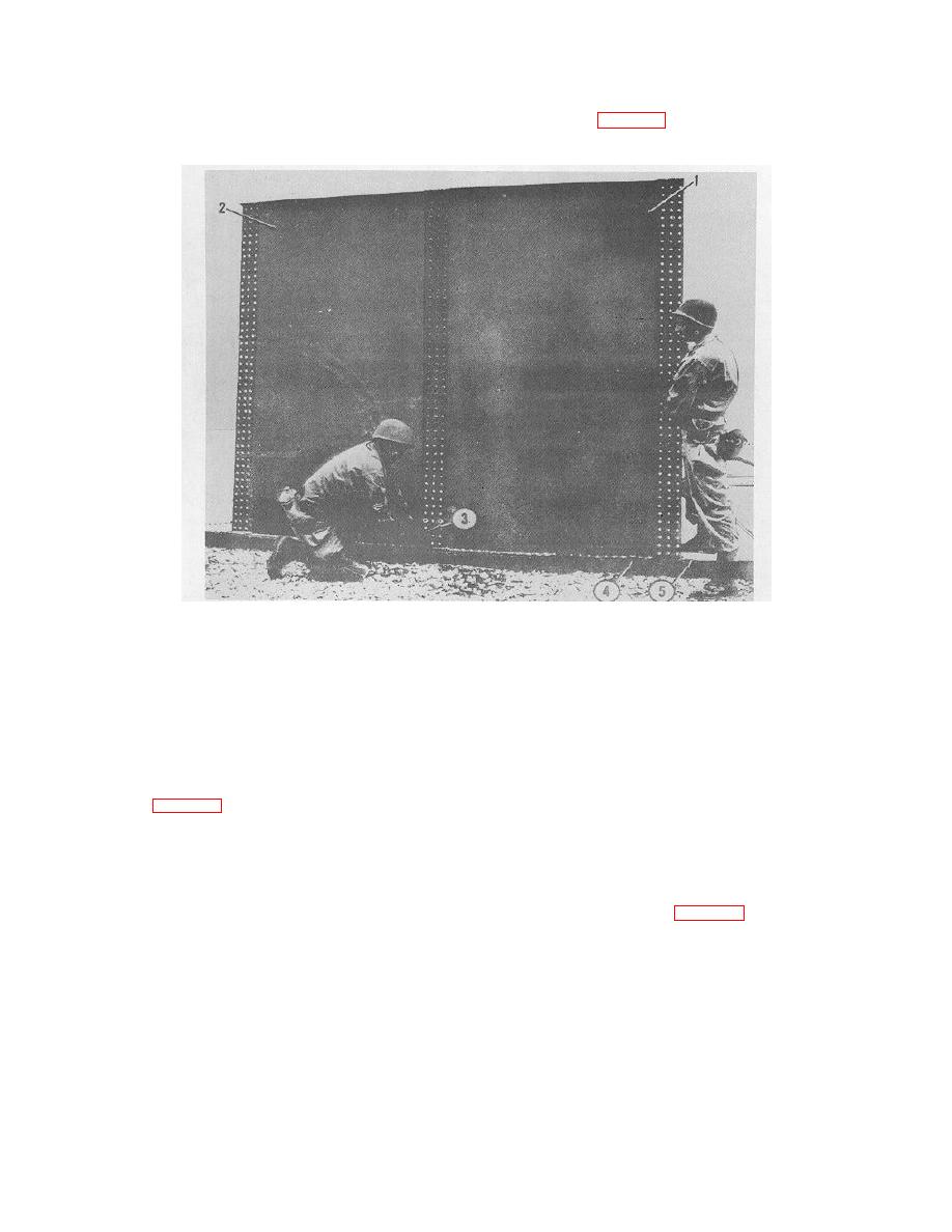
Figure 8-28. Installing first intermediate stave |
|
||
| ||||||||||
|
|
 TM 5-5430-209-12
(6) Install steel recessed washers, cup side down,
(1) Push 3 or 5 bolts flush with the gasket at right of
on all vertical seam bolts.
first stave (2, fig. 8-28).
c. Installing First Intermediate Stave.
1.
FIRST INTERMEDIATE STAV
2.
FIRST STAVE
3.
DRIFT PIN
4.
STRIP GASKET
5.
WEDGE GASKET
ME 5430-209-12/8-28
Figure 8-28. Installing first intermediate stave
(2) Set first intermediate stave (1) in position with
first intermediate stave or in a counterclockwise
its left seam outside the right seam of first stave (2).
direction around the bottom, following the same
Use drift pins (3) in open boltholes to aline the holes
procedure as in b and c above.
with bolts (2, fig. 8-27). Install nuts on every sixth or
NOTE
tenth bolt in each row.
Carry all staves for the second the third
NOTE
ring Into the tank before installing the last
As the remaining staves are installed,
two staves.
check carefully the position and tightness
(2) Install eight or nine staves with nuts in-stalled on
of all radii, wedge, and strip gaskets.
bolts as in c (2) above.
d. Installing Remaining Intermediate Staves.
(3) Install brace (3, fig. 8-29) at left seam of first
stave. Use a section of channel for the brace.
(1) Facing the outside of the second stave, install
remaining 34 staves, except the last, to the right of the
8-15
|
|
Privacy Statement - Press Release - Copyright Information. - Contact Us |
