 |
|||
|
|
|||
|
|
|||
| ||||||||||
|
|
 TM 5-5430-209-12
(5) Place wedge gasket (5) on each side of
(3) Place a bolt retaining board (6) under the
the center support base at the joining edges of adapter
bolting channel.
plate (1).
(4) Install strip gasket (4) along the full length
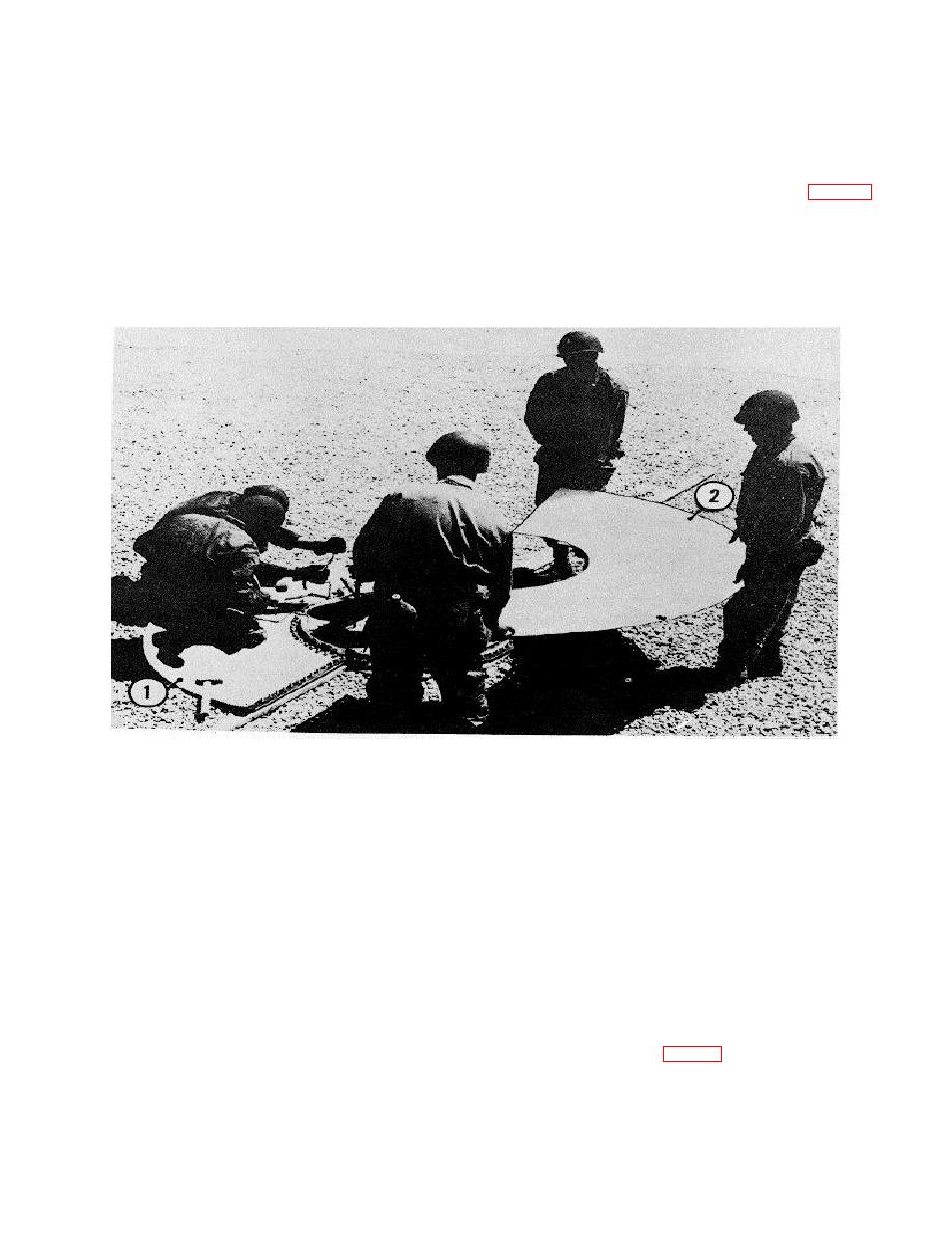
(6) Set bottom adapter plate (2, fig. 8-5) in
of the joining seam. Allow a 11/2 -bolt overlap at each
position on center support base. The joining edge of
end.
adapter plate (2) should overlap the joining edge of
CAUTION:
adapter plate (1).
Wedge gaskets must be used whenever
three plates or sections are jointed
together.
1.
BOTTOM ADAPTER PLATE
2.
BOTTOM ADAPTER PLATE
ME 5430-209-1`2/8-5
Figure 8-5. Installation
(7) Install steel recessed washer, cup side
inner plates and 37 outer plates. All inner plates are
down, and nut on each bolt protruding through bottom
interchangeable
and
all
outer
plates
are
adapter plate. Tighten bolts on center support base
interchangeable. The plates are first assembled by
flange first, then tighten lap joint bolts.
bolting the small end of the large plate on top of the
large end of the small plate. They are then treated as
(8) Place strip gasket around the outer bolt
37 one-piece sections, and are bolted to the center
circle of bottom adapter plates following the same
adapter plate assembly. When bottom is completely
procedure as in paragraph 8-lb (2), (4), (5), (6) and (7).
assembled, the section pattern reassembles a wheel.
Place wedge gasket under the gasket at lap seams of
bottom adapter plates. Insert 0-by 1/ inch bolts in 4-
b. Layout and Assembling Plates.
bolt hole channels. Insert channel assembly through
bottom adapter plates and gasket. Remove blocking.
(1) Place bolting channel under outer joining
seam of inner plate (1, fig. 8-6). Insert 1/2 by 1 /4 -inch
8-3.
Assembly of Bottom Sections
lap joint bolts (3) through all except the end boltholes of
the plate and channel.
a. General.
The assembled bottom section
consists of 74 Instapered, flat, steel plates. There are
37 inner of 74 tapered, flat, steel plates. There are 37
8-3
|
|
Privacy Statement - Press Release - Copyright Information. - Contact Us |
