 |
|||
|
|
|||
|
|
|||
| ||||||||||
|
|
 TM 32-5865-218-24&P
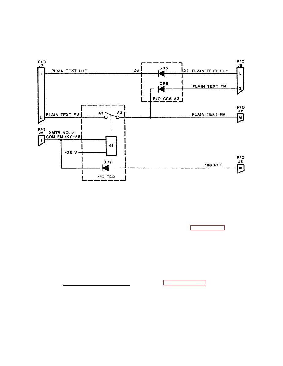
Countermeasures Control Monitor Circuits
Simplified Schematic Diagram
Lamp Control Circuit. As shown in figure 3-4, resistors
(4)
R20 thru R27, zener diodes VR2 and VR3, amplifier U2, and transistor
Q7 comprise a current-limiting circuit. The lamp control potentio-
meter in the external system equipment is connected to pins J8-S,
The LAMP DIMMER CONTROL input at pin J8-T varies the
J8-T, and J8-U.
transistor Q7 output to power transistor Q1 on the countermeasures
control chassis. The output of transistor Q1 is applied to terminal
stud E2 for distribution to external system equipment at connector
pins J2-g, J7-W, J7-X, and J8-J.
Refer to figure FO-2, sheet 1.
b. RF Coaxial Switch S1.
Switch S1 controls RF input/output signals between external system
During normal operation, the FM
equipments at connectors J4 and J5.
antenna control input from external system equipment is high (logic
1). When the control input goes low, the switch operates to connect
the BITE input from external system equipment at connector J1 to the
|
|
Privacy Statement - Press Release - Copyright Information. - Contact Us |
