 |
|||
|
|
|||
|
|
|||
| ||||||||||
|
|
 TM
9-2350-238-20-2
9
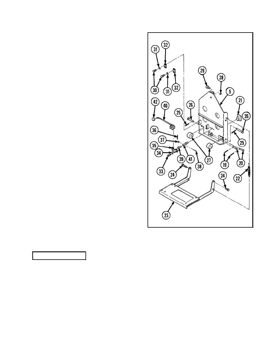
Remove two cotter pins (19), two head-
ed straight pins (20), vertical adjust seat
guide shoe (21).
10
Remove two helical extension springs
(22) from
rigger
and
gunner
seat
support
(23).
11
Remove two shoulder screws (24) and
rigger and gunner seat support (23) from
cab seat frame (5).
12
Remove two cotter pins (25), two head-
ed straight pins (26), and two seat back
rollers (27).
13
Remove
hexagon
plain
nut
(28)
and
nee-
dle bearing bolt (29) from cab seat frame
(5).
14
Remove four hexagon capscrews (30),
four Iockwashers (31), and two vertical
adjustment handle connecting links (32).
15
Remove two hexagon capscrews (33)
and two Iockwashers (34), releasing re-
taining strap (35) from cab seat frame
(5).
16
Remove cotter pin (36), flat washer (37),
and headed straight pin (38).
17
Remove helical spring (39), manual con-
trol lever (40), and headless shoulder pin
(41).
18
Remove knob (42) from manual control
lever
(40).
lNSPECTION/REPAIR
1 Check
for
broken,
damaged,
or
missing
parts.
2 If
cab seat frame
is
broken,
damaged,
or
missing,
repair
is
by
replacement
of
next
higher
assembly.
3 If
rigger
and
gunner
seat
support
is
broken,
damaged,
or
missing,
repair
is
by
replacement
of next higher assembly.
4 Repair
is
by
replacement
of
authorized
parts
(TM
9-2350-238-24P-2)
which
do
not
meet
in-
spection
criteria.
|
|
Privacy Statement - Press Release - Copyright Information. - Contact Us |