 |
|||
|
|
|||
|
|
|||
| ||||||||||
|
|
 TM 9-2350-238-20-1
NOTE
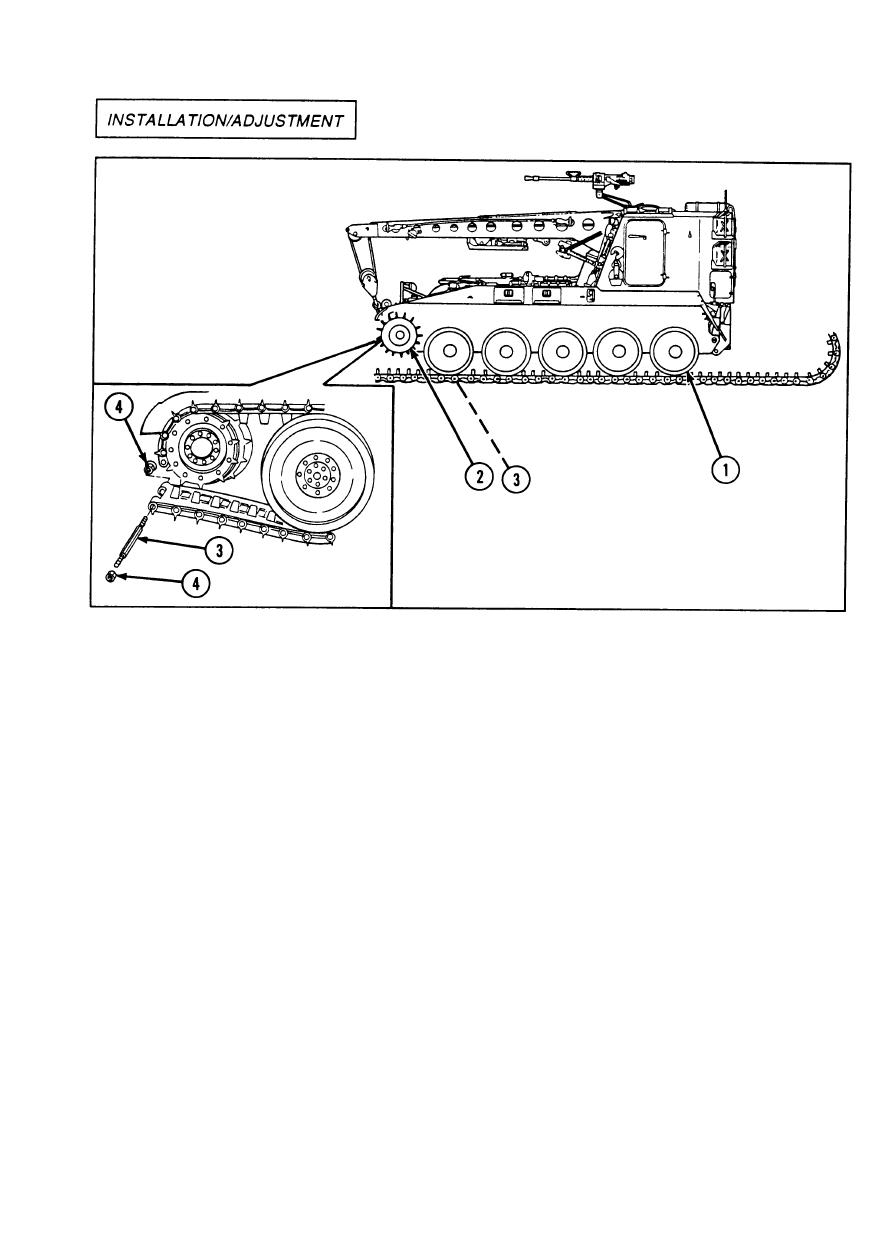
6 Start engine and slowly move vehicle
q Install
one track before removing
forward. Guide track over roadvvheels to
the other.
prevent end from getting caught between
roadwheels. When track reaches drive
Procedures are written for one
hub sprocket (2), pry or lift it over sprocket.
q
track, but apply to both tracks.
7 Using drive hub sprocket, bring ends of
1 Lay track in straight line in front of vehicle
track together.
with track shoe grousers forward and track
touching first roadwheel.
8 Remove drift pin.
2 Start engine and slowly drive onto track
9 Install two track connecting fixtures.
until 11 track shoes extend past hub of
trailing idler wheel (1).
10 Apply corrosion preventive compound to
track shoe link pin (3). Install track shoe
3 Stop engine. Leave parking brake off.
link pin (3) and two new self-locking nuts
(4). Tighten self-locking nuts to 180 to 200
4 Insert drift pin in last track shoe pin hole.
ft-lb (218 to 272 N-m).
5 Lift end of track over idler wheel (1).
2-877
|
|
Privacy Statement - Press Release - Copyright Information. - Contact Us |