 |
|||
|
|
|||
|
|
|||
| ||||||||||
|
|
 TM 9-2350-238-20-1
NOTE
Steps 9 thru 13 are written for brake
adjustment when powerplant is
removed.
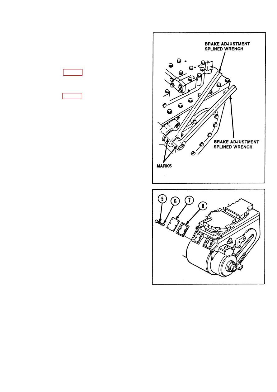
Place brake adjustment splined wrench
9
(item 35, appx G) on right brake apply
shaft (large shaft).
Place brake adjustment splined wrench
10
(item 34, appx G) on left brake apply shaft
(small shaft).
11
Mark both brake adjustment splined
wrenches so that marks align with
RELEASE mark.
Using brake adjustment splined wrenches,
12
torque both brake apply shafts to 90 ft-lb
(10 N-m).
13
Check that marks are aligned with APPLY
mark. If marks do not align with APPLY
mark, continue adjustment procedure with
powerplant installed.
NOTE
Steps 14 thru 19 are written for brake
adjustment when powerplant is in-
stalled.
14
Remove 12 hexagon head capscrews (5)
and 4 Iockwashers (6).
Remove two brake adjustment covers (7)
15
and two gaskets (8).
2-825
|
|
Privacy Statement - Press Release - Copyright Information. - Contact Us |
