 |
|||
|
|
|||
|
|
|||
| ||||||||||
|
|
 TM 9-2350-238-20-1
1
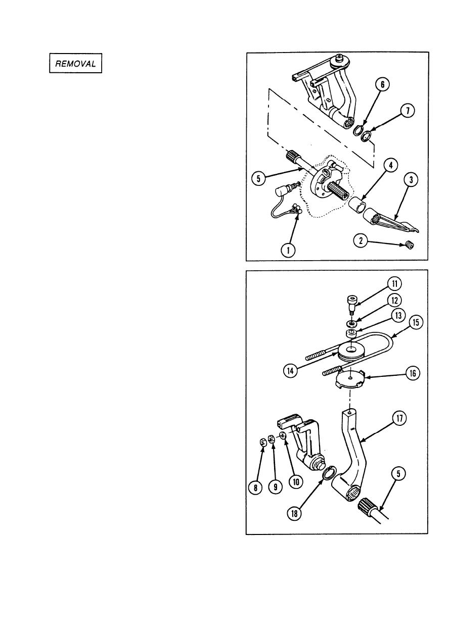
Disconnect three electrical connectors (1)
of brake warning sensitive switch.
2
Remove pipe plug (2).
Remove brake pedal (3) and tube coupling
3
(4) from straight shaft (5).
4
Remove retaining ring (6) and ring spacer
(7) .
Remove two self-locking nuts (8), two
5
hexagon plain nuts (9), and two flat
washers (10).
Remove shoulder screw (11) and flat
6
washer (12).
Remove sleeve bearing (13), groove
7
pulley (14), brake control cable (15), and
brake clip assembly (16).
Support manual control lever (17) and pull
8
straight shaft (5) into driver's compartment.
Remove manual control lever (17).
9
Remove retaining ring (18) from inside
10
manual control lever (17).
2-821
|
|
Privacy Statement - Press Release - Copyright Information. - Contact Us |