 |
|||
|
|
|||
|
|
|||
| ||||||||||
|
|
 TM 9-2350-238-20-1
2-73. MAINTENANCE OF DRIVER'S INSTRUMENT PANEL (GAGE) (CONT).
REASSEMBLY
NOTE
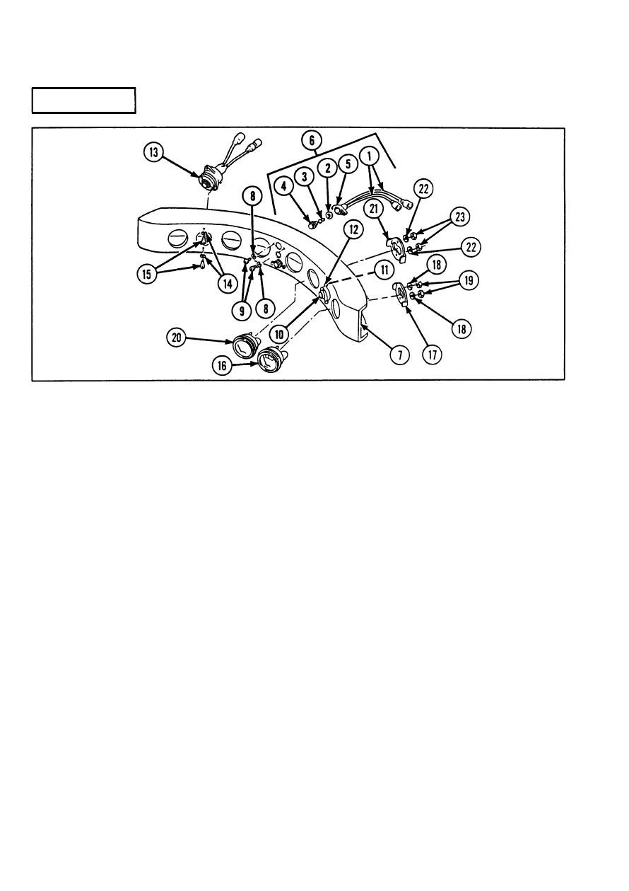
Steps 1 thru 3 are written for one panel light, but apply to both.
1 If removed, install new electrical wires (1).
2 Install flat washer (2), LED (3), and cap (4) in socket housing (5).
machine screws (9).
lockwashers (11) and two machine screws (12). Untag and connect electrical leads to
connectors of generator charge warning light.
5 Install engine and transmission warning light (13) in instrument panel (7), and secure with two
new Iockwashers (14) and two machine screws (15). Untag and connect electrical leads to
connectors of engine and transmission warning light.
(17), two lockwashers (18), and two hexagon plain nuts (19). Untag and connect electrical lead
to connector on back side of battery/generator voltmeter.
7 Install engine oil pressure gage (20) in instrument panel (7), and secure with mounting clamp
(21 ), two lockwashers (22), and two hexagon plain nuts (23). Untag and connect two electrical
leads to connectors on back side of engine oil pressure gage.
2-576
|
|
Privacy Statement - Press Release - Copyright Information. - Contact Us |